

Width-adjustable vehicle loading ramp
- Summary
- Abstract
- Description
- Claims
- Application Information
AI Technical Summary
Benefits of technology
Problems solved by technology
Method used
Image

Examples
first embodiment
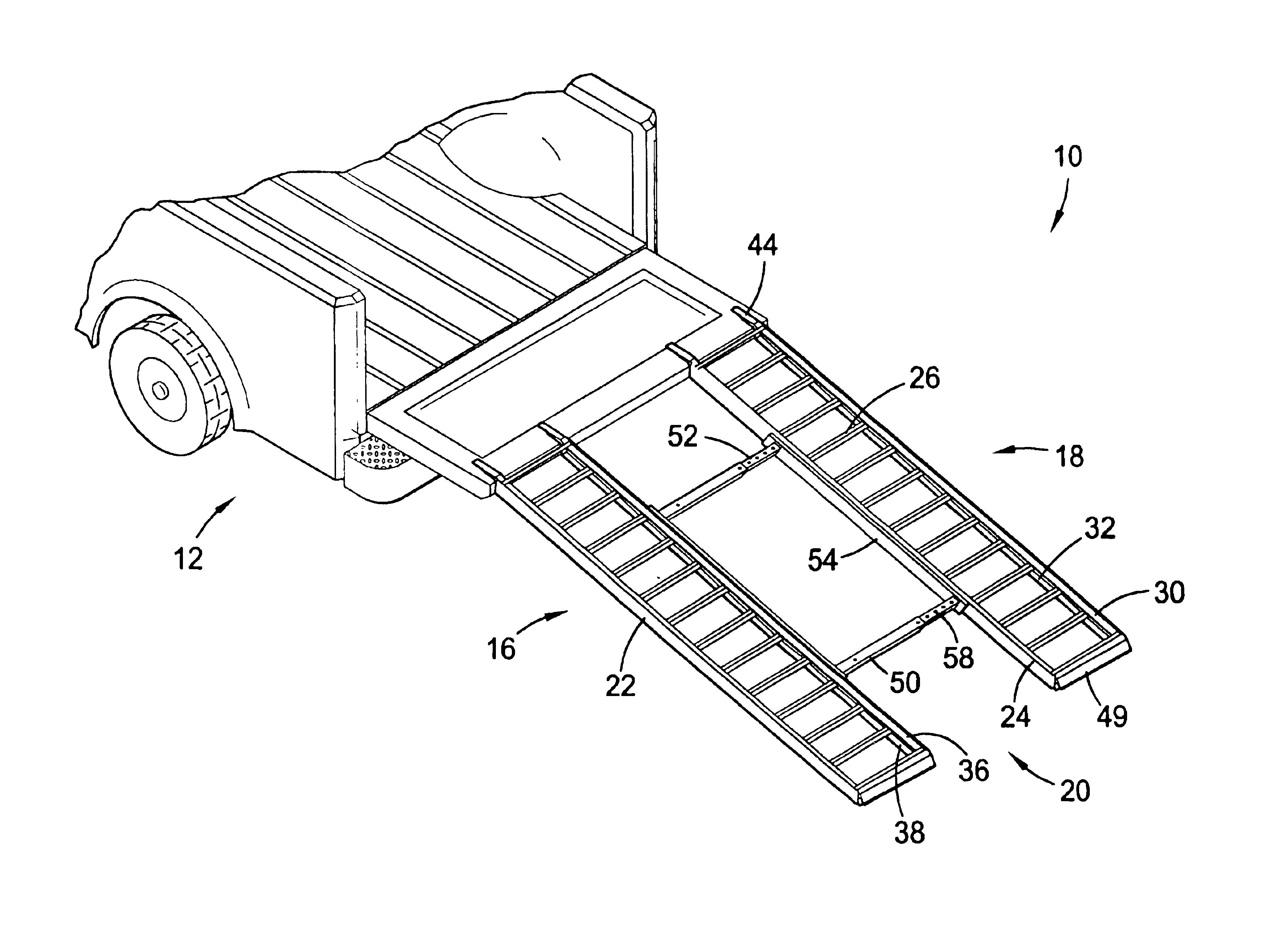
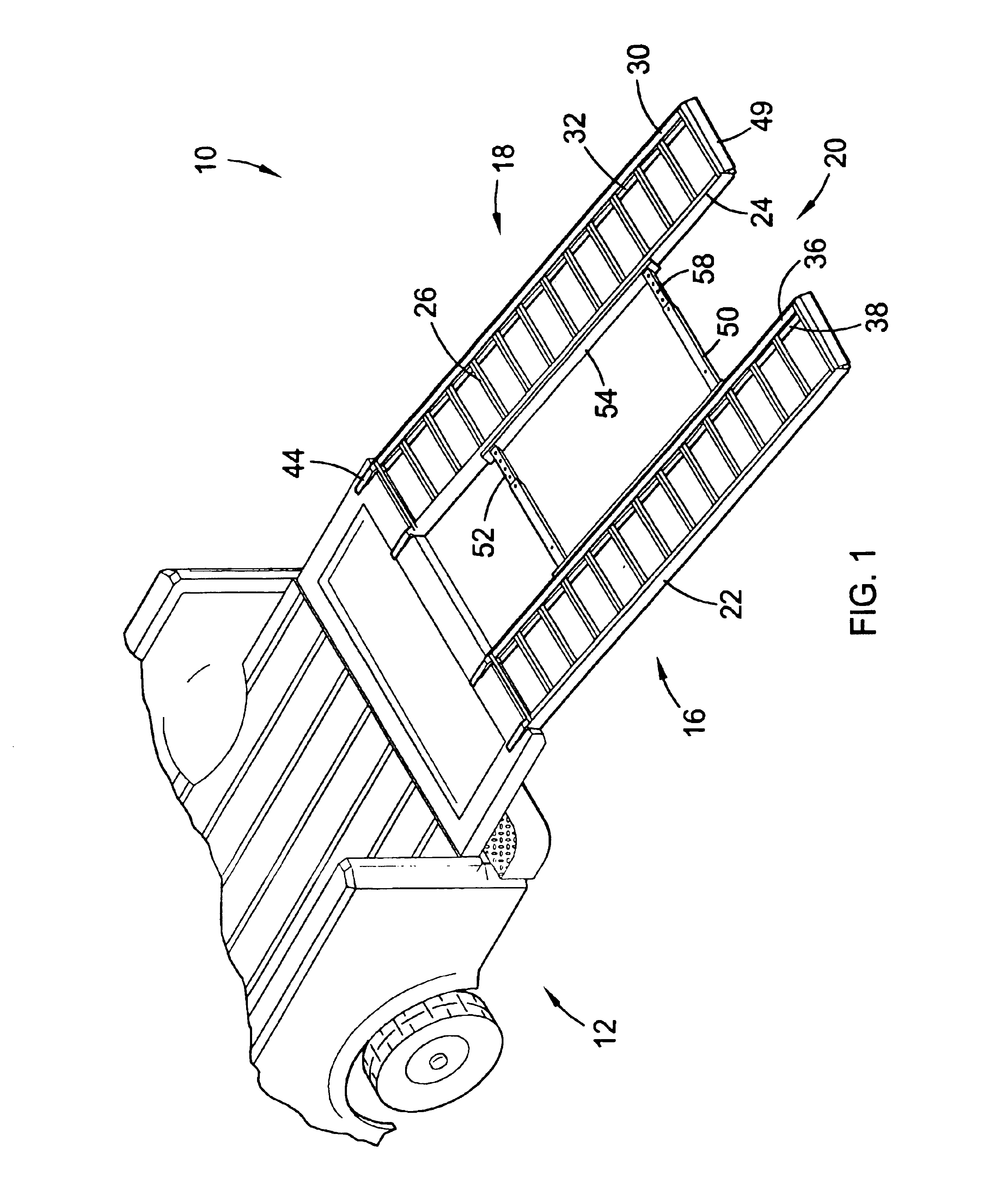
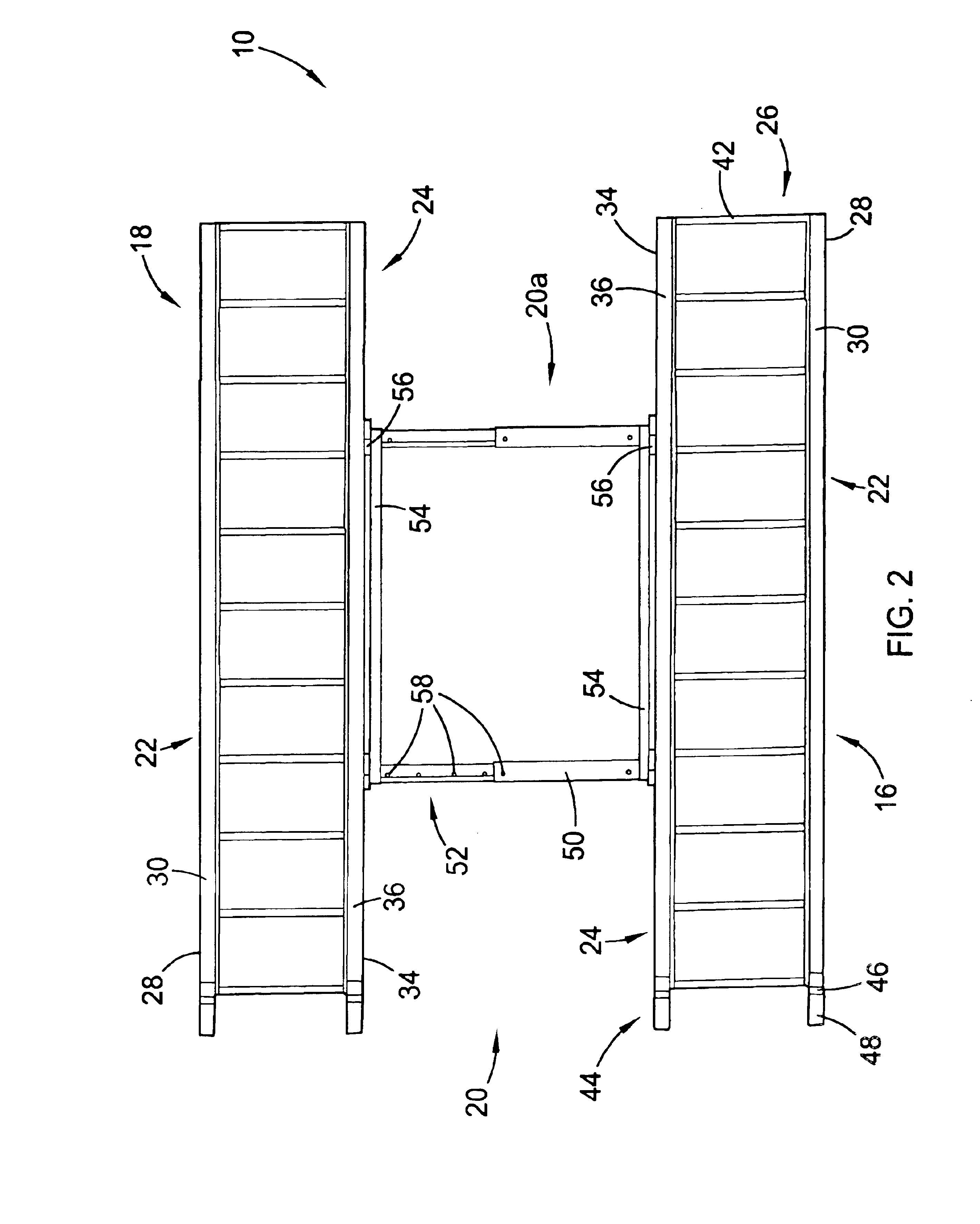
For example, the brace 20a preferably includes at least one sleeve 50 secured to the inside surface 34 of the inside rail 24 of the first platform 16 and at least one expansion support 52 secured to the inside surface 34 of the inside rail 24 of the second platform 18. The sleeve 50 and the expansion support 52 are preferably constructed from an extruded aluminum alloy that resists rust, but may be constructed of any substantially rigid material that resists rust, such as composites and / or polymers. Alternatively, the sleeve 50 and the expansion support 52 may be constructed of a rigid material that is susceptible to rust, such as steel. The sleeve 50 is preferably a square tube structure presenting an approximately two inch square external cross-section, an approximately one and one half inch square internal cross-section, and an approximately fourteen inch length. The sleeve 50 may be secured directly to the first platform 16 or though a bracket 54. Additionally, the sleeve 50 may...
second embodiment
Referring now to FIGS. 4 and 5, the brace 20b preferably includes a plurality of tubular receivers 60 and a plurality of fixed length substantially U-shaped bars 62 that rigidly connect opposing pairs of the receivers 60. The receivers 60 and the bars 62 are preferably constructed from an extruded aluminum alloy that resists rust, but may be constructed of any substantially rigid material that resists rust, such as composites and / or polymers. Alternatively, the receivers 60 and the bars 62 may be constructed of a rigid material that is susceptible to rust, such as steel. The receivers 60 are preferably welded to the inside surfaces 34 of the inside rails 24 of the platforms 16,18. The receivers 60 are preferably approximately three inches tall, preferably have an approximately one half inch internal diameter, and are preferably spaced approximately twenty-four inches apart along the inside surfaces 34 of the platforms 16,18. Although, as will become evident, the receivers 60 may be ...
third embodiment
Referring now to FIGS. 6-8, the brace 20c preferably includes a plurality of tubular receivers 60 substantially identical to those described above and a frame 68 that can be mated to the receivers 60 in two or more orientations. The frame 68 is preferably constructed of four bars 62 similar to those described above, with two of the bars 62 having an approximately twenty inch substantially horizontal portion 64 and two of the bars 62 having an approximately thirty inch substantially horizontal portion 64. The bars 62 of the frame 68 are preferably welded together to form a rectangular structure having an approximately thirty inch length and an approximately twenty inch width.
The receivers 60 are preferably spaced such that the vertical portions 66 of the bars 62 of the frame 68 may be mated with the receivers 60 along the length or the width of the frame 68. As shown in FIG. 6, with the frame 68 mated to the receivers 60 along its length, the platforms 16,18 are spaced approximately ...
PUM
 Abstract
Description
Claims
Application Information