Adjustable security enclosure

a security enclosure and adjustable technology, applied in the direction of machine supports, projectors, domestic objects, etc., can solve the problems of theft of electronic equipment, high cost of replacing stolen equipment, and particularly problematic theft of electronic equipmen

Active Publication Date: 2006-04-18
HARD STEAL SECURITY
View PDF35 Cites 38 Cited by
  • Summary
  • Abstract
  • Description
  • Claims
  • Application Information

AI Technical Summary

Benefits of technology

[0007]According to one aspect of the invention, there is provided an apparatus for securing an audio video device such as a projector. This apparatus is mountable to a ceiling drop pipe and comprises a cage for housing the device and a connector assembly for connecting the cage to a fixture such as a ceiling mounted drop pipe. The cage has a plurality of interconnected members that together define an enclosure for housing a projector and impeding removal of the projector from the cage. At least some of the members are connected together by at least one member fastener that can be unfastened from inside the cage, such that the position of at least some of the members can be adjusted relative to other members so that the size of the enclosure can be adjusted to fit the projector snugly therein, thereby impeding access to the fastener. When securing projectors, the connector assembly is connectable to a ceiling drop pipe, and has a cage mounting portion mounted to at least one of the members by at least one removable connector assembly fastener that can be unfastened from inside the cage.
[0008]Two of the members can be top plates connected to each other by at least one of the member fasteners, and laterally adjustable relative to each other such that the width of the cage can be adjusted. In such case, the cage mounting portion of the connector assembly can be mounted to one of the top plates. Also, some of the members can be top plate members that extend downwardly from the top plates; in such case, some of the members can be vertically extending members that extend generally vertically and are adjustably connected to the top plate members by at least one of the member fasteners such that the height of the cage can be adjusted. Furthermore, some of the members can be lateral support members for supporting a projector and which extend laterally from the vertically-extending members and are adjustably connected to each other by at least one of the member fasteners such that the width of the cage can be adjusted, for example, to match the width of the top plates.

Problems solved by technology

Portable electronic equipment such as projectors are prone to theft.
Replacing stolen equipment can be expensive and distracting.
Electronic equipment theft is particularly problematic for organizations that must expose their equipment to the public.
Projectors that are placed on tables can be removed from the room after each use; however, transporting and setting up the projector in the room each time it is to be used tends to be time consuming and is undesirable when the room is frequently used for presentations.
Such ceiling mounting hardware is not particularly secure—a thief can simply remove the fasteners that attach the adjustment bracket to the mounting plate, or remove the fasteners in the adjustment bracket itself, or remove the fasteners which attach the mounting plate to the projector.
Disadvantageously, the cage is not adjustable in size to accommodate projectors of different sizes; use of the cage to enclose smaller projectors tend to be aesthetically unpleasing.
More problematic is that the device is simply an enclosure that uses the projector's existing mounting hardware.
Furthermore, the cage must be completely removed from the projector to allow access to the projector for regular maintenance, which is time consuming.
However, like the Chief device, the Peerless device includes a cage that is not adjustable to accommodate projectors of different sizes.
This security device is also problematic as It must be completely removed to allow access to the projector for regular maintenance.

Method used


Image

  • Adjustable security enclosure
  • Adjustable security enclosure
  • Adjustable security enclosure

Examples


Embodiment Construction

[0025]Directional terms such as “top”, “bottom”, and “upwards” are used in the following description for the purpose of providing relative reference only, and are not intended to suggest any limitations on how any apparatus is to be positioned during use, or to be mounted in an assembly.

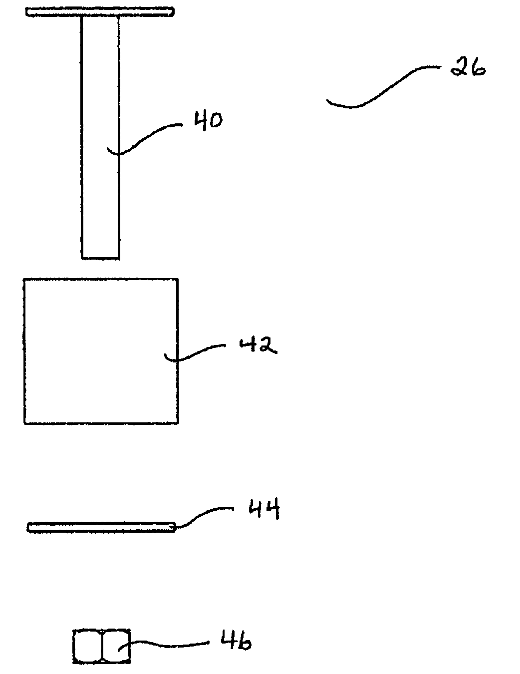
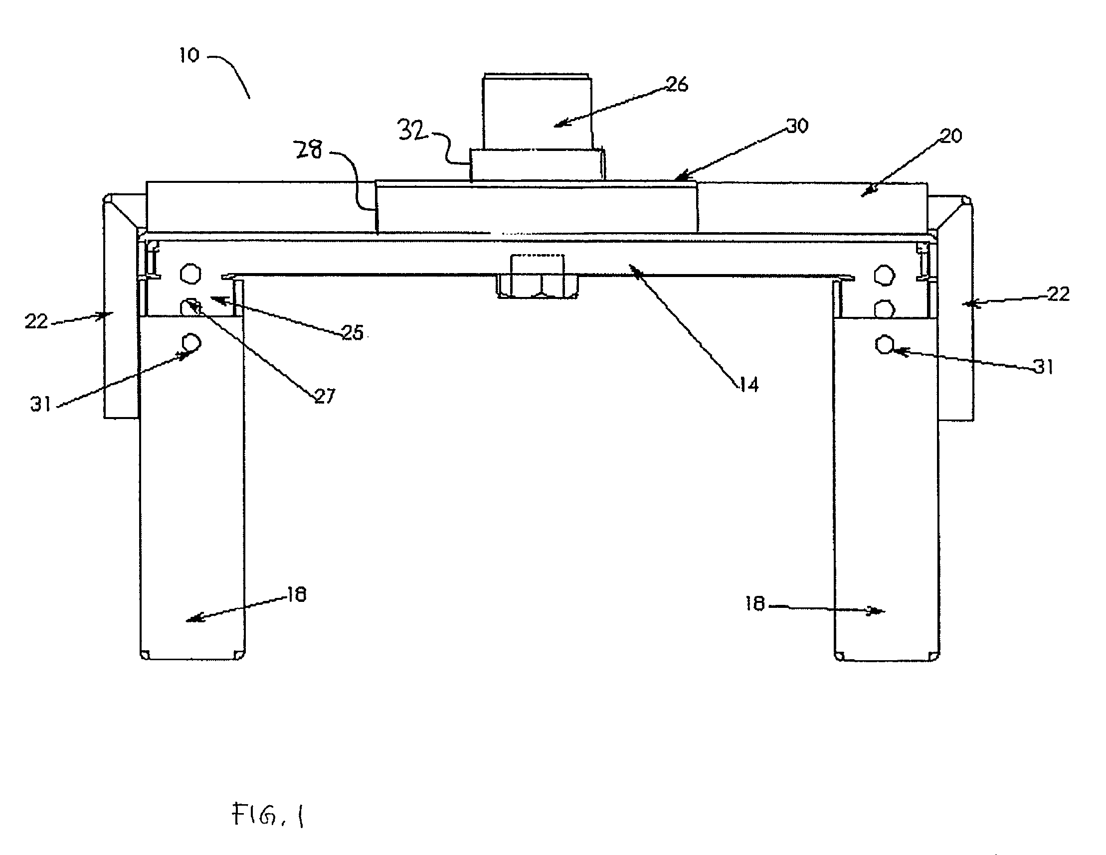
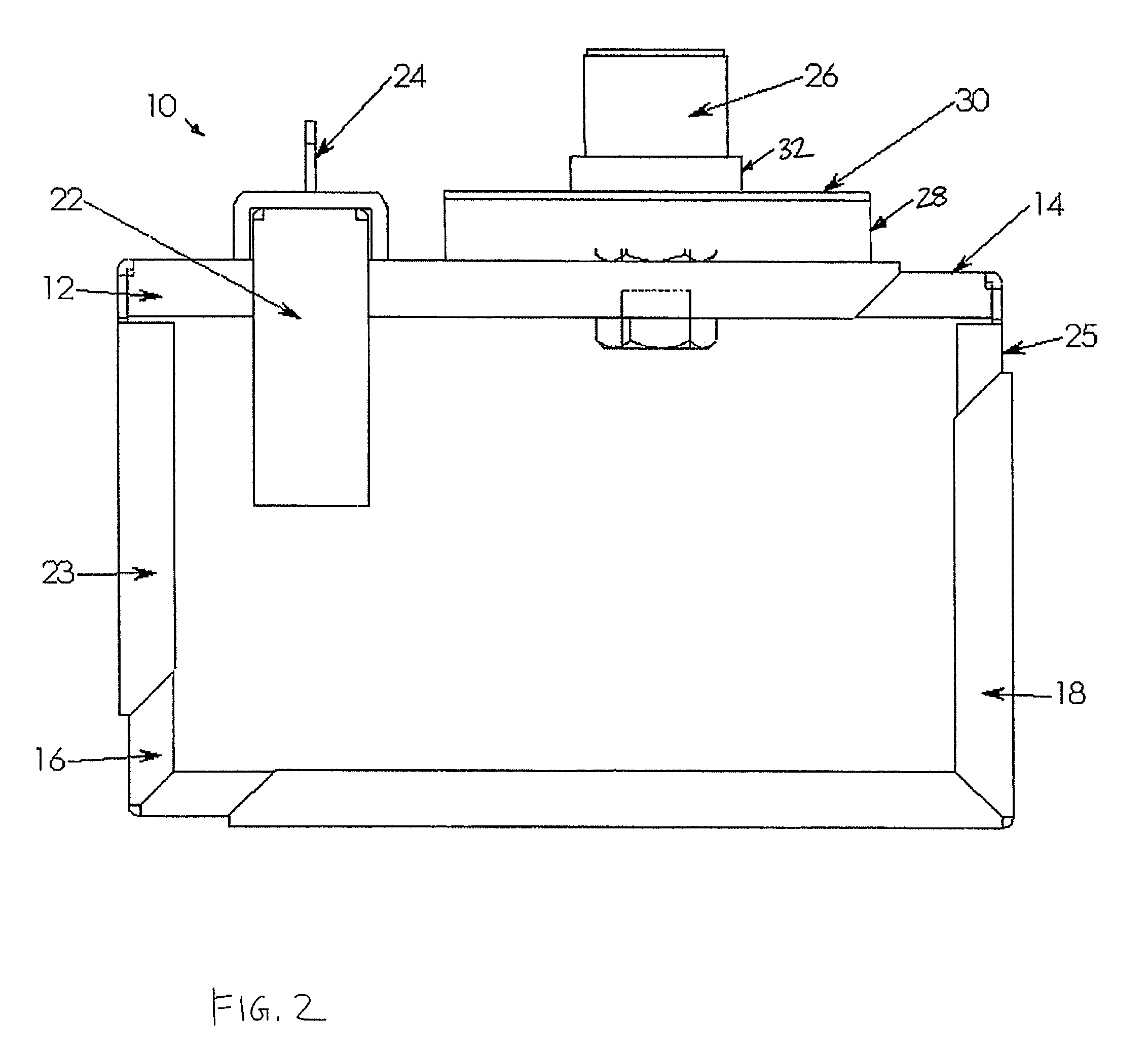
[0026]According to one embodiment of the invention and referring to FIGS. 1 to 4, a security enclosure 10 for a video projector (not shown) is securely mountable to a drop pipe (not shown) that extends downwards from a ceiling. The security enclosure 10 can be adjusted to house projectors of various sizes, and is engineered to resist removal of a projector housed therein, as well as to resist removal of the security enclosure 10 from the drop pipe. Such projectors include data projectors and home entertainment audio-video projectors.

Components

[0027]The security enclosure 10 generally comprises a cage assembly for housing the projector and a connector assembly for connecting the cage assembly to the d...


PUM


Abstract

This invention relates to an apparatus for securing a projector. The apparatus is mountable to a ceiling drop pipe and comprises a cage and a drop pipe connector assembly. The cage has a plurality of interconnected members that together define an enclosure for housing a projector and impeding removal of the projector from the cage. At least some of the members are connected together by a member fastener that is fastenable only from inside the cage. The position of at least some of the members can be adjusted relative to other members so that the size of the enclosure can be adjusted to fit the projector snugly therein, thereby impeding access to the fastener.

Description

FIELD OF THE INVENTION[0001]This invention relates generally to adjustable security enclosures, and in particular, to security enclosures that are adjustable to enclose portable electronic equipment such as projectors, that are of different sizes and dimensions.BACKGROUND OF THE INVENTION[0002]Portable electronic equipment such as projectors are prone to theft. Replacing stolen equipment can be expensive and distracting. Electronic equipment theft is particularly problematic for organizations that must expose their equipment to the public. For example, schools and conference centres have meeting rooms that are equipped with presentation equipment, such as computers, and video I data projectors. Projectors can be portable units placed on top of a table and removed after each use. Projectors that are placed on tables can be removed from the room after each use; however, transporting and setting up the projector in the room each time it is to be used tends to be time consuming and is u...

Claims


Application Information

Patent Timeline
Patent Type & Authority Patents(United States)
IPC IPC(8): G03B21/14F16M13/00G03B21/22
CPCF16M11/14F16M13/02G03B21/22G03B21/14F16M13/027G03B21/145
Inventor CHALLIS, ROGER W.
Owner HARD STEAL SECURITY
Why Eureka
Try Eureka