Impact drill

a drill bit and impact technology, applied in the field of impact drill bit, can solve the problems of small adjustment width of stroke force, weakened and possible broken fragile partner parts, and achieve the effects of compressing spring volume, reducing stroke force, and reducing biasing force of spring

Inactive Publication Date: 2006-07-11
KOKI HLDG CO LTD
View PDF21 Cites 32 Cited by
  • Summary
  • Abstract
  • Description
  • Claims
  • Application Information

AI Technical Summary

Benefits of technology

[0032]It is an object of the invention to provide an impact drill that solves the above-mentioned problems associated with the prior art. It is a further object of the invention to provide an impact drill in which a state of generating a set stroke force is maintained even if the biasing force is excessive, the adjustment width of the stroke force is large, and the vibration transmitted to the user is reduced.
[0040]Since the amount of back movement of the spindle and the rotational ratchet is regulated, the work may be performed with such a pressing force that the spindle comes into contact with the regulating member, whereby even though the pressing force is further increased, the compression amount of the spring is not increased, and the biasing force of the spring is not increased, so that the stroke force does not become excessive to prevent the partner member from being broken.
[0041]When the stroke force is weakened, the amount of back movement of the spindle and the rotational ratchet is regulated to be smaller, whereby the intermeshing depth of ratchets is not only shallower, but also the compression amount of the spring is reduced, so that the biasing force of the spring can be weakened. Accordingly, the stroke force can be weaker than conventionally, and therefore made adequate for the fragile partner member.
[0042]Moreover, when the stroke force is intensified, the amount of back movement of the spindle and the rotational ratchet is regulated to be larger, whereby the intermeshing depth of ratchets is not only deeper, but also the compression amount of the spring is increased, so that the biasing force of the spring can be intensified. Accordingly, the stroke force can be stronger than conventionally, and therefore made adequate for the partner member difficult to be drilled.

Problems solved by technology

In Japanese Patent No. 3,002,284, it is difficult to keep the pressing force constant, and particularly when a small stroke force is attained by the weak pressing force, the stroke force is too excessive if the pressing force is too strong, resulting in a problem that the fragile partner member is possibly broken.
In JP-A-62-74582 the vibration transmitted from the spindle to the housing is not relieved, and the intermeshing depth of ratchets may be reduced but the relative position of the ratchet and the spring is invariable, resulting in a problem that the biasing force of the spring can not be weakened.
That is, with this constitution, the intermeshing depth of ratchets may be changed but the relative position of the ratchet and the spring is invariable, resulting in a problem that the adjustment width of the stroke force is small.
In Japanese Patent No. 2754047, JP-A-3-178708, and JP-A-4-240010, the vibration transmitted from the spindle to the housing is not relieved, and the biasing force of the spring may be changed but the intermeshing depth of ratchets may not be changed, resulting in a problem that the adjustment width of the stroke force is small.

Method used


Image

  • Impact drill
  • Impact drill
  • Impact drill

Examples


first embodiment

[0062]FIGS. 8, 9, 10 and 11 are constitutional views of a main portion of an impact drill according to a first embodiment of the invention. Firstly, referring to FIG. 8, the constitution of each part will be described below.

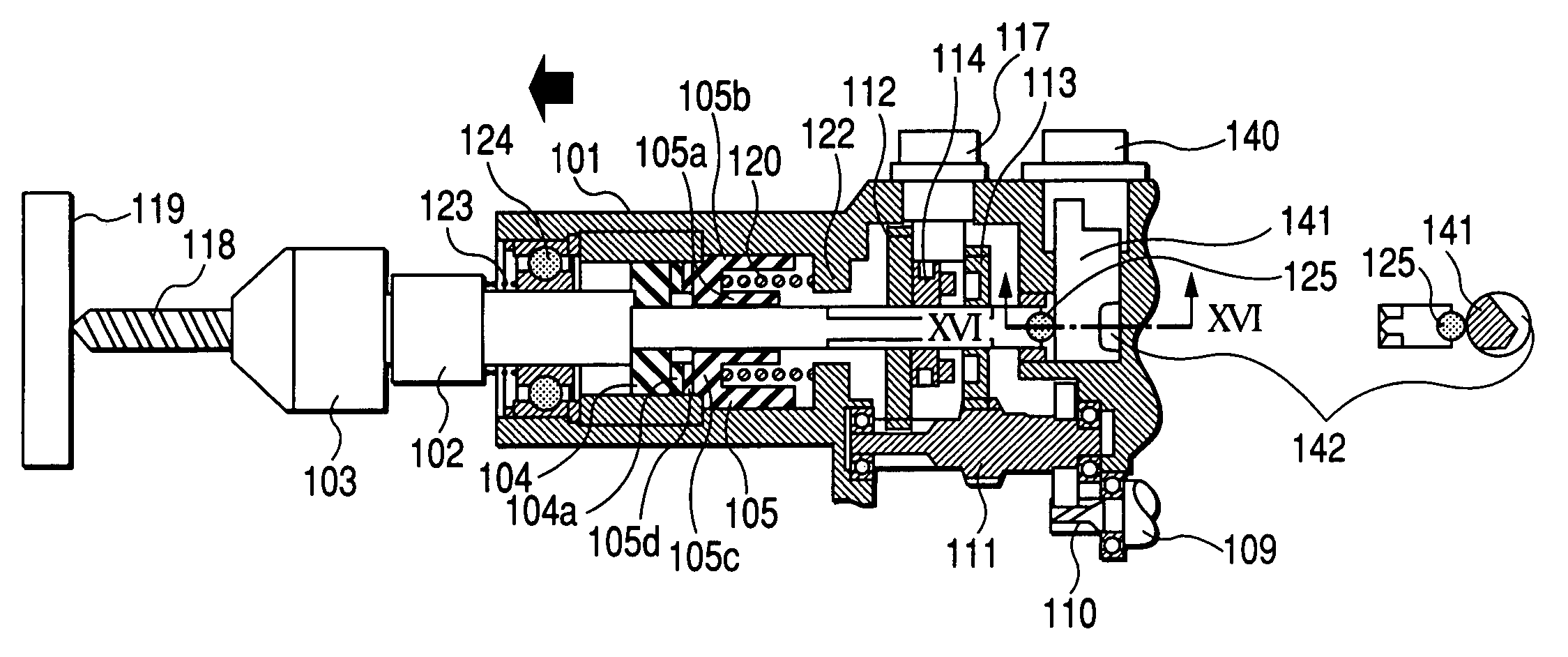
[0063]A spindle 102 is provided in a main frame portion 101 and moved forward (to the left in the figure) or backward (to the right in the figure) relative to a workpiece 119. A chuck 103 for mounting a drill bit 118 is provided at the top end of the spindle 102. A first ratchet 104 and a second ratchet 105 are provided in the almost central part of the main frame portion 101. The first ratchet 104 is rotated along with the spindle 102 and moved axially, and has serrated irregularities 104a on one face. The second ratchet 105 is formed with serrated irregularities 105d on a bottom portion 105c. Also, the second ratchet 105 has a dual cylindrical shape, in which an inner cylindrical portion 105a slides on the spindle 102 and an outer cylindrical portion 105b slide...

second embodiment

[0078]FIG. 12 shows a second embodiment of the invention, which has one feature in that the steel ball 125 provided at a rear end of the spindle 102 is contacted with a plate-like change lever 143 having the step portions different in the depth.

[0079]That is, FIG. 17 shows the plate-like change lever 143 in enlargement, which has a face 143a having the largest step W3, a face 143b having the next largest step W2, a face 143c having the smallest step W1, and a face 143d without step. This plate-like change lever 143 is provided movably in the vertical direction, whereby the contact face with the steel ball 125 is changed in accordance with its position. FIGS. 12 to 15 are cross-sectional views of the impact drill as looked from the above (opposite to the side where the handle portion 6 is provided in FIG. 1). Accordingly, since the change lever 143 is provided movably in the left-to-right direction of the impact drill, one end of the change lever 143 can be pressed by a forefinger, a...


PUM

PropertyMeasurementUnit
movementaaaaaaaaaa
distanceaaaaaaaaaa
depthaaaaaaaaaa

Abstract

An impact drill includes a first ratchet rotating along with a spindle and movable in an axial direction, a second ratchet engaged with the first ratchet and movable in a axial direction but unrotatable, and a spring provided between the second ratchet and a partial member of a housing. An amount of movement of the spindle in the axial direction is regulated, so that the pressing force is too excessive, the restoring force of the spring urging the second ratchet is controlled to maintain a state of generating a set stroke force.

Description

BACKGROUND OF THE INVENTION[0001]1. Field of the Invention[0002]The present invention relates to an impact drill for use in a drilling operation on a concrete, mortar or tile, for example, and more particularly to an impact drill having a drill mode for performing a drilling operation by rotating a drill bit and an impact drill mode for performing a drilling operation by rotating and vibrating the drill bit.[0003]2. Description of the Related Art[0004]FIG. 1 shows a conventional example of the impact drill of this kind. In FIG. 1, reference numeral 1 denotes a main frame portion that forms an outer shell of the impact drill and has the self-contained parts at predetermined positions, comprising a gear cover 17, an inner cover 18, an outer cover 19, a housing 7 and a handle portion 6. Reference numeral 2 denotes a spindle inserted transversely through the gear cover 17, and 3 denotes a drill chuck attached at the top end of the spindle. A rotational ratchet 4 is mounted near the cent...

Claims


Application Information

Patent Timeline
Patent Type & Authority Patents(United States)
IPC IPC(8): B23B45/16B25D11/00B25D11/10B25D16/00B25D17/24B25F5/00B28D1/14B28D1/26E02D7/02
CPCB25D11/005B25D11/106B25D16/003B25D16/006B25F5/001B25D2216/0023B25D2250/021B25D2250/095B25D2250/201B25D2250/321B25D2250/371B25D2216/0038
Inventor SAITO, TAKUMAOHTSU, SHINKIWATANABE, HIDEKITOUKAIRIN, JUNICHI
Owner KOKI HLDG CO LTD
Why Eureka
Try Eureka