
Hot plate structure for automatic cleaning of collection cups

A technology for automatic cleaning and collecting cups, which is applied in the direction of cleaning hollow objects, cleaning methods and utensils, chemical instruments and methods, etc., can solve the problems of time-consuming and laborious, and achieve the effects of low energy consumption, long life and stable performance

Active Publication Date: 2017-05-10
SHENYANG KINGSEMI CO LTD
View PDF7 Cites 0 Cited by
  • Summary
  • Abstract
  • Description
  • Claims
  • Application Information

AI Technical Summary

Problems solved by technology

Moreover, the chemicals sprayed in different processes are also inconsistent. After the process is completed, there are often some chemical agents left on the CUP component (collection cup). At present, after the wafer is sprayed, it is necessary to spray the CUP component (Referring to the collection cup that is directly sprayed with chemicals) It is disassembled from the equipment for cleaning, and then reinstalled on the equipment after cleaning, which is time-consuming and laborious

Method used


Image

  • Hot plate structure for automatic cleaning of collection cups
  • Hot plate structure for automatic cleaning of collection cups
  • Hot plate structure for automatic cleaning of collection cups

Examples


Embodiment Construction

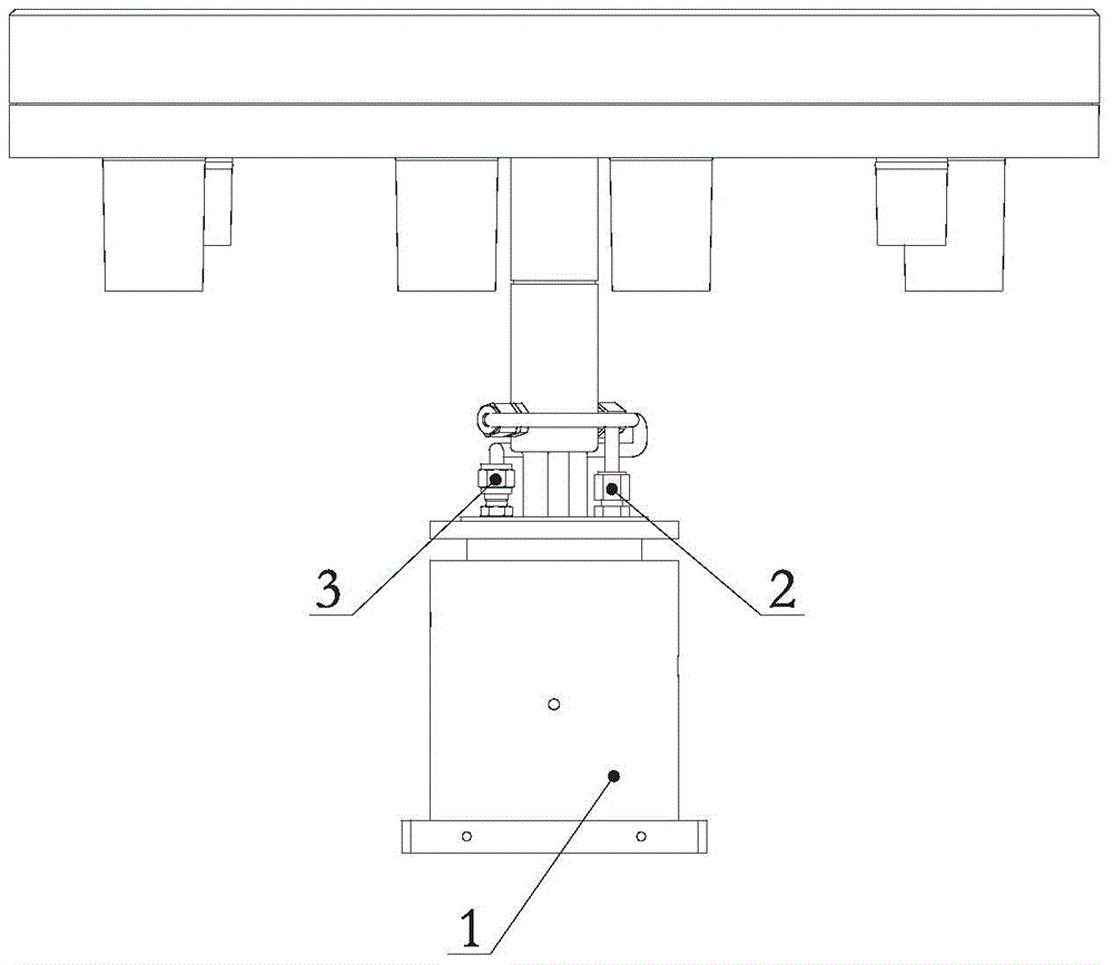
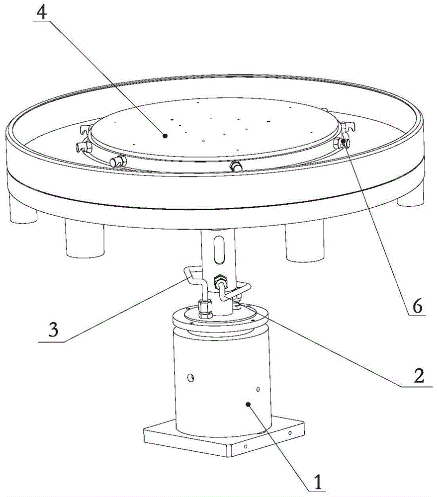
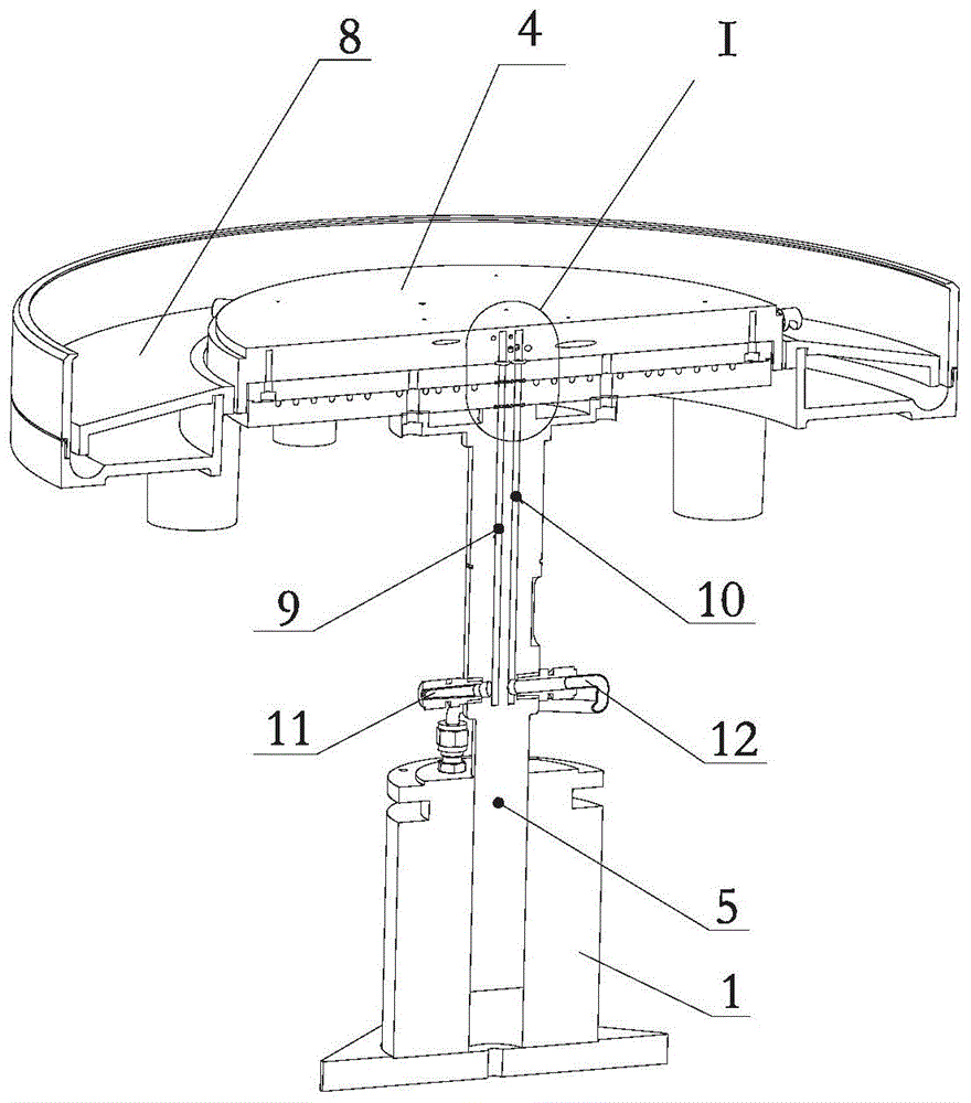
[0028] The present invention will be further described below in conjunction with the drawings.

[0029] Such as Figure 1-7 As shown, the present invention includes a gas-liquid mixing slip ring 1, an upper hot plate 4, a rotating shaft 5, a nozzle 6 and a collecting cup 8. The upper hot plate 4 and the gas-liquid mixing slip ring 1 are respectively arranged on the upper and lower sides of the rotating shaft 5. At both ends, the collecting cups 8 are arranged on the outer lower side of the upper hot plate 4. The rotating shaft 5 is provided with a rotating shaft gas passage 9 and a rotating shaft liquid passage 10 along the axial direction. The lower end outer circumference of the rotating shaft 5 is provided with a rotating shaft gas passage 9 and a rotating shaft liquid passage 10 respectively. The rotary shaft air inlet 11 and the rotary shaft liquid inlet 12, the rotary shaft air inlet 11 and the rotary shaft liquid inlet 12 respectively communicate with the air outlet and th...


PUM


Abstract

The invention relates to the field of semiconductor equipment, in particular to a hot plate structure for cleaning a collection cup automatically. The hot plate structure comprises a gas-liquid mixture sliding ring, an upper hot plate, a rotating shaft, a nozzle and the collection cup. The upper hot plate and the gas-liquid mixture sliding ring are arranged at the upper end and the lower end of the rotating shaft respectively. The collection cup is arranged on the lower side of the upper hot plate. The rotating shaft is provided with a rotating shaft gas channel and a rotating shaft liquid channel in the axial direction. A rotating shaft gas inlet and a rotating shaft liquid inlet are formed in the external circumference of the lower end of the rotating shaft. The rotating shaft gas inlet and the rotating shaft liquid inlet are communicated with a gas outlet and a liquid outlet of the end of a rotor of the gas-liquid mixture sliding ring respectively. The upper hot plate is provided with an upper hot plate gas channel and an upper hot plate liquid channel which are communicated with the rotating shaft gas channel and the rotating shaft liquid channel respectively. The nozzle communicated with the upper hot plate liquid channel is arranged on the outer cylinder surface of the upper hot plate. The upper surface of the upper hot plate is provided with a plurality of vacuum adsorption holes communicated with the upper hot plate gas channel. According to the hot plate structure, the function of cleaning the collection cup automatically is achieved, and meanwhile vacuum adsorption on wafer can be achieved on the surface of the upper hot plate.

Description

Technical field [0001] The invention relates to the field of semiconductor equipment, in particular to a hot plate structure for automatically cleaning a collecting cup. Background technique [0002] At present, with the diversification of semiconductor manufacturing processes, many process treatments in equipment are becoming more and more complicated, and it is often necessary to spray the wafers during the manufacturing process. Depending on the process, the spraying time may vary. In addition, the sprayed chemicals in different manufacturing processes are also inconsistent. After the process is completed, there are often some chemical residues on the CUP components (collecting cups). At present, after the wafer is sprayed, it is necessary to spray the CUP components at regular intervals. (Refers to the collection cup directly sprayed with chemicals) It is removed from the equipment for cleaning, and then reinstalled on the equipment after cleaning, which is time-consuming and...

Claims


Application Information

Patent Timeline
Patent Type & Authority Patents(China)
IPC IPC(8): B08B9/28
Inventor 童宇波
Owner SHENYANG KINGSEMI CO LTD
Learn More