
Tube conveying device for machining of electrical heated tube

A technology of transmission device and electric heating tube, which is applied in the attachment device of shearing machine, shearing device, metal processing equipment, etc., can solve problems such as being unable to meet modern industrial production.

Active Publication Date: 2016-03-30
YANGZHONG TONGLI IND CO LTD
View PDF6 Cites 11 Cited by
  • Summary
  • Abstract
  • Description
  • Claims
  • Application Information

AI Technical Summary

Problems solved by technology

The electric heating tube needs to transmit its metal tube shell during the processing, but the existing transmission device has great limitations and cannot meet the needs of modern industrial production

Method used


Image

  • Tube conveying device for machining of electrical heated tube
  • Tube conveying device for machining of electrical heated tube

Examples


Embodiment Construction

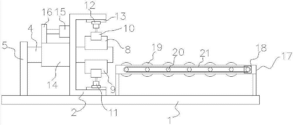
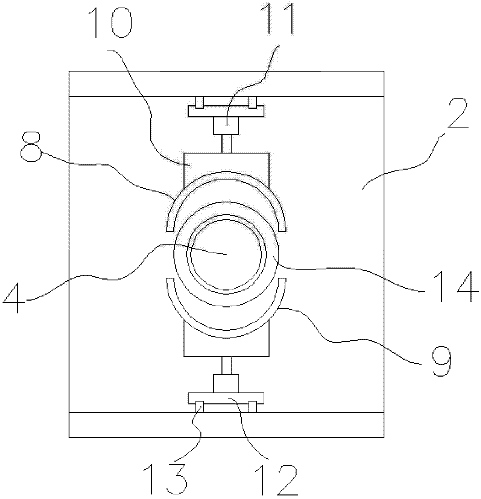
[0020] Such as figure 1 and figure 2 The shown pipe transmission device for electric heating tube processing includes a base 1, a U-shaped bracket 2, a pipe clamp, a support cylinder 4, an ejector sleeve 14, a transmission bracket 17 and a roller transmission device. The U-shaped The bracket 2 is connected to the base 1, and the pipe clamp is composed of an upper clamp 8 and a lower clamp 9, and the upper clamp 8 and the lower clamp 9 are respectively connected to the upper and lower side walls of the U-shaped bracket 2 through a clamping mechanism. Above, the support cylinder 4 is placed horizontally, one end of which passes through the U-shaped bracket 2 and extends between the upper clamp 8 and the lower clamp 9, and the other end is connected with the support plate 5, and the support plate 5 is vertical Connected to the base 1, the side of the ejection sleeve 14 is annular, the ejection sleeve 14 is set on the outside of the support sleeve 4, the inner wall of the ejecti...


PUM


Abstract

The invention relates to a tube conveying device for machining of an electrical heated tube. The tube conveying device comprises a base, a U-type support, a tube clamp, a supporting barrel, an ejector sleeve, a conveying support and a roller conveying device, wherein the U-type support is connected to the base; the tube clamp is composed of an upper clamp body and a lower clamp body which are connected to the upper side wall and the lower side wall of the U-type support through clamping mechanisms respectively; the supporting barrel is horizontally arranged; one end of the supporting barrel penetrates through the U-type support to extend to the position between the upper clamp body and the lower clamp body; the lateral face of the ejector sleeve is in a ring shape; the supporting barrel is sleeved with the ejector sleeve; an interval exists between the inner wall of the ejector sleeve and the outer wall of the supporting barrel; the ejector sleeve is connected with a hydraulic cylinder through a horizontal moving board; a through hole is formed in the position, opposite to the ejector sleeve, of the U-type support. By means of the design, the tube conveying device has the advantages of being simple in structure, easy to manufacture, practical and efficient.

Description

technical field [0001] The invention relates to an electric heating tube processing machine, in particular to a pipe material transmission device for electric heating tube processing. Background technique [0002] Tubular electric heating elements (electric heating tubes) are made of metal tubes (including stainless steel and copper tubes), and spiral electric heating alloy wires (nickel-chromium, iron-chromium alloy) are uniformly distributed along the central axis of the tube, and the gaps are filled and compacted to have good insulation and heat conduction. High-performance magnesia sand, both ends of the nozzle are sealed with silica gel, this metal armored heating element can heat air, metal molds and various liquids. The metal tube shell of the electric heating tube needs to be transported during the processing, but the existing transport device has great limitations and cannot meet the needs of modern industrial production. Contents of the invention [0003] The te...

Claims


Application Information

Patent Timeline
Patent Type & Authority Applications(China)
IPC IPC(8): B23D33/02
CPCB23D33/02
Inventor 莫兆根
Owner YANGZHONG TONGLI IND CO LTD
Learn More