Buffered adjustable synchronous pneumatic fixture

A technology of synchronous positioning and pneumatic clamping, which is applied in the direction of positioning device, clamping device, clamping device, etc., and can solve problems such as unclamping, easy damage of motor, and deviation of plate size.

Active Publication Date: 2016-03-30
SIMTO GROUP
View PDF7 Cites 6 Cited by
  • Summary
  • Abstract
  • Description
  • Claims
  • Application Information

AI Technical Summary

Problems solved by technology

[0003] Manual fixture: the clamping process requires human participation, time-consuming and inaccurate positioning;
[0004] Electric special fixture: the tightening process does not require human participation, and the action is fast; but due to the size deviation of the plate, the plate is too large, and the motor is easy to be damaged; the plate is too small, it cannot be clamped; and it is not suitable for asymmetrical positioning

Method used


Image

  • Buffered adjustable synchronous pneumatic fixture
  • Buffered adjustable synchronous pneumatic fixture
  • Buffered adjustable synchronous pneumatic fixture

Examples


Embodiment Construction

[0026] The present invention will be further described below in conjunction with the accompanying drawings, but the present invention is not limited to the following examples.

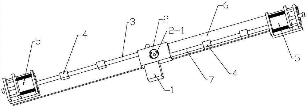
[0027] Such as figure 1 As shown, a pneumatic clamp with cushioning and adjustable synchronous positioning includes a strip-shaped base plate 6, the left rack 3 is positioned on the left side of the base plate through several guide blocks 4, and the right rack 7 is also positioned on the left side of the base plate through several right guide blocks. The right side of the base plate; each guide block is separated by a certain distance, and the bottom is respectively fixed on the base plate and guide holes are opened on the guide block to facilitate the sliding of the left rack (or right rack).

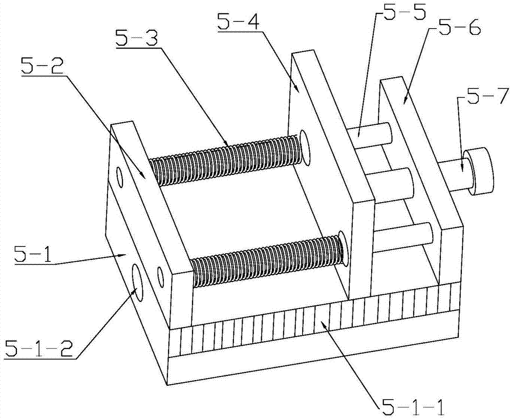
[0028] The left end of the left rack and the right end of the right rack are respectively connected with a clamping table 5, and the power device positioned in the center of the bottom plate applies driving for...


PUM


Abstract

The invention relates to a buffered adjustable synchronous pneumatic fixture, aiming at proving a device which can meet the requirement of automatic alignment and positioning of square tool plates with different sizes and has the characteristics of being not easy to damage a power original part, adjustable in splint position and relatively high in efficiency. According to the technical scheme, the buffered adjustable synchronous pneumatic fixture comprises a stripe bottom plate, a left rack and a right which are parallelly positioned on the left side and the right side of the bottom plate by guide blocks and capable of moving oppositely along the length direction of the bottom plate, and a power device for simultaneously applying driving force to the left rack and the right rack; the left end of the left rack and the right end of the right rack are respectively connected with a clamping table; and the power device comprises a cylinder fixed in the center of the bottom plate by a gear seat, a lower gear which is arranged at the internal bottom end of the gear seat and capable of performing power transfer with a cylinder driving shaft via a circular rack, and an upper gear which is coaxially arranged with the lower gear via a gear rotating shaft and is simultaneously meshed with the left rack and the right rack.

Description

technical field [0001] The invention relates to a process equipment, in particular to an adjustable synchronous positioning pneumatic clamp with buffer. Background technique [0002] At present, positioning fixtures are commonly used in the centering and positioning process of square plate processing tools, and the requirements for the speed, positioning accuracy, and versatility of positioning fixtures are getting higher and higher. The existing centering and positioning devices for square plates are mainly divided into the following two types: [0003] Manual fixture: the clamping process requires human participation, time-consuming and inaccurate positioning; [0004] Electric special fixture: the tightening process does not require human participation, and the action is fast; but due to the size deviation of the plate, the plate is too large, and the motor is easy to be damaged; the plate is too small, it cannot be clamped; and it is not suitable for asymmetrical positi...

Claims


Application Information

Patent Timeline
Patent Type & Authority Applications(China)
IPC IPC(8): B23Q3/08
CPCB23Q3/08B23Q2703/04
Inventor 杨太玮童俊华贺磊盈程培林唐曲曲
Owner SIMTO GROUP
Why Eureka
Try Eureka