Torque wrench provided with locking device

A technology of locking device and torque wrench, which is applied in the field of torque wrench, can solve problems such as inconvenient use, deformation and damage, and achieve the best convenience effect

Inactive Publication Date: 2016-03-30
禾嘉兴有限公司
View PDF7 Cites 6 Cited by
  • Summary
  • Abstract
  • Description
  • Claims
  • Application Information

AI Technical Summary

Problems solved by technology

However, during switching of the locking sleeve 50, the O-ring 58 stops the locking ball 60, so there is no clear positioning feeling when switching between the locked position and the unlocked position, and the user will easily ignore whether It has been adjusted to the required position, which is easy to cause inconvenience in use. At the same time, after a period of use, the O-ring 58 may have the risk of deformation and damage due to the environment

Method used


Image

  • Torque wrench provided with locking device
  • Torque wrench provided with locking device
  • Torque wrench provided with locking device

Examples


Embodiment Construction

[0043] In order to illustrate the central idea of ​​the present invention expressed in the column of the above-mentioned summary of the invention, it is expressed in specific embodiments. Various objects in the embodiments are drawn according to proportions, sizes, deformations or displacements suitable for illustration, rather than drawn according to the proportions of actual components, and are described first.

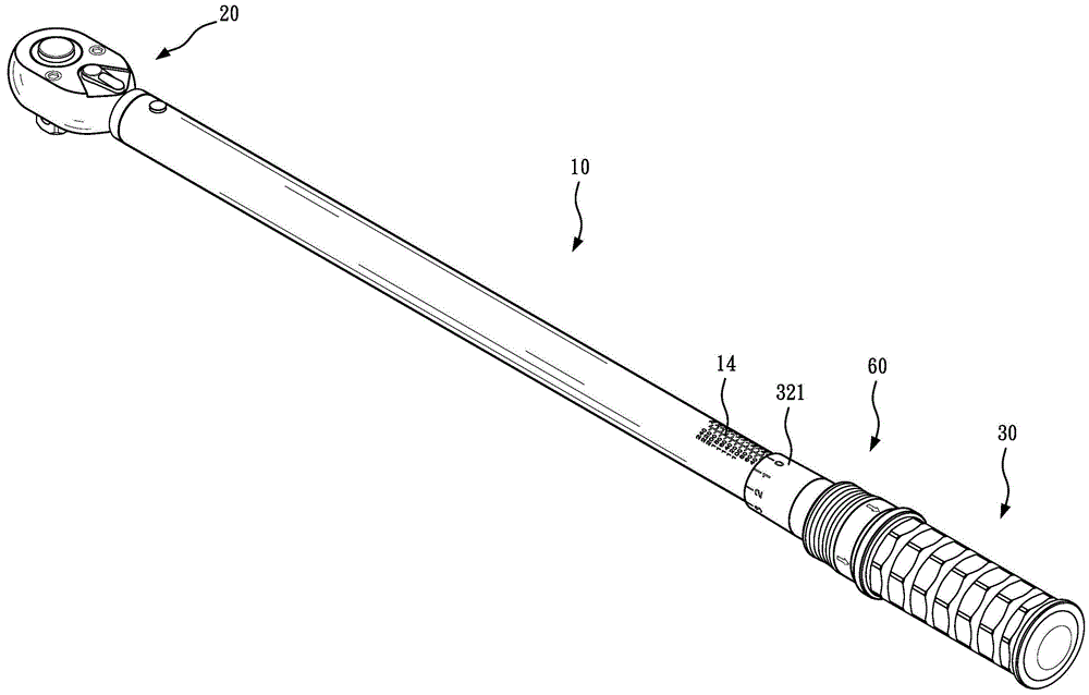
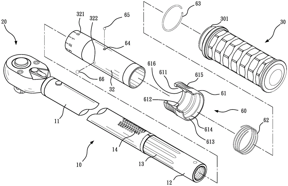
[0044] Such as Figure 1 to Figure 4 As shown, the present invention is a torque wrench with a locking device, comprising:

[0045] A hollow main rod body 10 includes a first end 11 and a second end 12 . Wherein, a plurality of positioning grooves 13 are recessed on the outer periphery of the second end 12 parallel to the axial direction, and a plurality of torque value display numbers 14 are further provided on the periphery of the main rod body 10 .

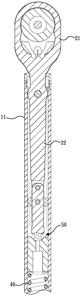
[0046] A tool piece 20 includes a head section 21 and a rod section 22 , the head section 21 can be a tool such ...


PUM


Abstract

The invention provides a torque wrench provided with a locking device. The torque wrench provided with the locking device comprises a hollow main rod body, an adjustment handle and the locking device. The locking device moves in the axial direction between a locking position and a non-locking position along the main rod body. The locking device can limit the rotation, relative to the main rod body, of the adjustment handle when located in the locking position. The adjustment handle can rotate relative to the main rod body when the locking device is located in the non-locking position, so that torsion adjustment is conducted. Sounds can be produced when the locking device is adjusted and switched between the locking position and the non-locking position.

Description

technical field [0001] The invention relates to a torque wrench, especially a torque wrench with a locking device. Background technique [0002] The known torque wrench has a hollow main rod body, a tool part for fitting a nut or a bolt and a rotatable adjustment handle are respectively provided at both ends, and the main rod body is inserted between the tool part and the adjustment handle. A clutch assembly and a spring are also provided. Wherein, the adjustment handle can be pushed against the spring by rotating to change the pre-force of the spring, and the clutch assembly can produce a clutch action when the torsion force on the tool is greater than the elastic pre-force of the spring To limit the torque on the tool parts. Moreover, the clutch assembly can generate a knocking sound during the clutch action to remind the user of the problem of excessive force. So as not to damage the nuts or bolts. [0003] Such as U.S. Patent No. 5,129,293, which discloses a torque w...

Claims


Application Information

Patent Timeline
Patent Type & Authority Applications(China)
IPC IPC(8): B25B23/142
Inventor 陈竹村
Owner 禾嘉兴有限公司
Why Eureka
Try Eureka