Automatic splicing mechanism

An automatic splicing and splicing system technology, which is applied to other connectors, vehicle parts, transportation and packaging, etc., can solve the problems of time-consuming and labor-intensive, increase the workload and labor intensity of workers, and achieve reduced workload, simple structure and convenient installation Effect

Inactive Publication Date: 2016-03-30
BEIJING XINGDA TECH DEV
View PDF5 Cites 0 Cited by
  • Summary
  • Abstract
  • Description
  • Claims
  • Application Information

AI Technical Summary

Problems solved by technology

[0002] At this stage, a large number of tooling vehicles are needed to assist in the installation of equipment in large factories. Tooling vehicles need to be spliced ​​and linked during certain installation work. The tra

Method used


Image

  • Automatic splicing mechanism
  • Automatic splicing mechanism
  • Automatic splicing mechanism

Examples


Embodiment Construction

[0021] In order to make the purpose, technical solutions and advantages of the embodiments of the present invention clearer, the technical solutions in the embodiments of the present invention will be clearly and completely described below in conjunction with the drawings in the embodiments of the present invention. Obviously, the described embodiments It is a part of embodiments of the present invention, but not all embodiments. Elements and features described in one drawing or one embodiment of the present invention may be combined with elements and features shown in one or more other drawings or embodiments. It should be noted that representation and description of components and processes that are not related to the present invention and known to those of ordinary skill in the art are omitted from the drawings and descriptions for the purpose of clarity. Based on the embodiments of the present invention, all other embodiments obtained by persons of ordinary skill in the ar...


PUM


Abstract

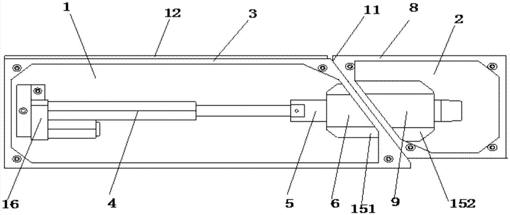
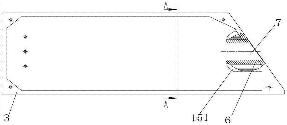
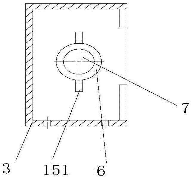
The invention provides an automatic splicing mechanism which comprises an active splicing part and a passive splicing part, wherein the active splicing part is provided with an active splicing part box body, an electric push rod, a splicing pin shaft and an active splicing part guide cylinder, wherein a through hole is formed in the active splicing part guide cylinder, one end of the splicing pin shaft is connected with the electric push rod, and the other end of the splicing pin shaft is movably inserted into the through hole of the active splicing part guide cylinder; the passive splicing part is provided with a passive splicing part box body and a passive splicing part guide cylinder, wherein a containing hole is formed in the passive splicing part guide cylinder; and the splicing pin shaft can pass through the through hole in the active splicing part guide cylinder to extend into the containing hole in the passive splicing part guide cylinder under the drive of the electric push rod. The automatic splicing mechanism is simple in structure, convenient to install and simple in operation; and the splicing operation is mainly realized by pushing the splicing pin shaft by virtue of the electric push rod, thereby reducing the working difficulty of the splicing operation, reducing the workload of the splicing operation and saving time and labor.

Description

technical field [0001] The invention relates to a splicing mechanism, in particular to an automatic splicing mechanism for vehicles, which is mainly used for mutual splicing and combination in the field of tooling vehicles. Background technique [0002] At this stage, a large number of tooling vehicles are needed to assist in the installation of equipment in large factories. Tooling vehicles need to be spliced ​​and linked during certain installation work. The traditional method uses manual splicing, which is time-consuming and laborious, and increases the workload and labor intensity of workers. , designing an automatic splicing mechanism has become an urgent problem to be solved. Contents of the invention [0003] A brief overview of the invention is given below in order to provide a basic understanding of some aspects of the invention. It should be understood that this summary is not an exhaustive overview of the invention. It is not intended to identify key or critic...

Claims


Application Information

Patent Timeline
IPC IPC(8): B60D99/00
CPCB60D99/00
Inventor 张军奎庞龙亮杨辉杨谦周平来
Owner BEIJING XINGDA TECH DEV
Why Eureka
Try Eureka