Vehicle thrust rod assembly, adjusting method thereof and vehicle suspension mechanism

A thrust rod and assembly technology, applied in the field of automobile chassis, can solve problems such as non-adjustable length, and achieve the effects of improving versatility, reducing use costs, and avoiding waste

Active Publication Date: 2016-03-30
SHAANXI HEAVY DUTY AUTOMOBILE
View PDF6 Cites 6 Cited by
  • Summary
  • Abstract
  • Description
  • Claims
  • Application Information

AI Technical Summary

Problems solved by technology

[0003] In view of this, the present invention aims to provide a vehicle thrust rod assembly and its adjustment method, and an automobile suspension mechanism. The length of the thrust rod is adjustable and detachable. The problem of adjusting the length, on the other hand, it only needs to replace a small number of components to deal with common failure modes, improve the commonality of parts between different types of thrust rod assemblies, reduce the actual cost of use, and bring greater economic benefits

Method used


Image

  • Vehicle thrust rod assembly, adjusting method thereof and vehicle suspension mechanism
  • Vehicle thrust rod assembly, adjusting method thereof and vehicle suspension mechanism
  • Vehicle thrust rod assembly, adjusting method thereof and vehicle suspension mechanism

Examples


Embodiment Construction

[0028] In order to make the purpose, technical solution and advantages of the present invention clearer to those skilled in the art, the present invention will now be described in further detail in combination with preferred embodiments with reference to the accompanying drawings.

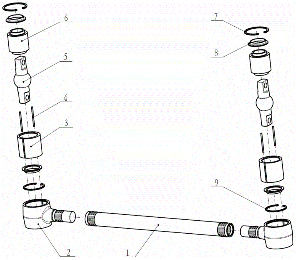
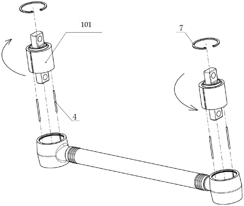
[0029] like figure 1 As shown, the new thrust rod assembly for vehicles according to the present invention includes a shaft tube 1, a spherical shell 2, an eccentric sleeve 3, a lock pin 4, a mandrel 5, a rubber 6, a second retaining spring 7, and an end cover 8 , the first snap ring 9. The spherical head shell 2 is connected with the shaft tube 1 by heat riveting. The eccentric sleeve 3 is pressed into the ball shell 2 at both ends of the assembly, its circumferential positioning is realized by the lock pin 4, and the axial positioning is realized by the flange at the lower end of the ball shell 2 and the retaining spring 7; Use transition fit. The end caps 8 are placed at both ends of the ecce...


PUM


Abstract

The invention provides a vehicle thrust rod assembly, an adjusting method thereof and a vehicle suspension mechanism. The vehicle thrust rod assembly is adjustable in length and detachable, thereby being convenient to maintain. The thrust rod assembly is characterized in that two ball head shells are connected to the two ends of a shaft pipe in a hot riveting mode, two eccentric bushings are pressed into the ball head shells at the two ends, positioning of the eccentric bushings in the circumferential direction is achieved through lock pins, and positioning of the eccentric bushings in the axial direction is achieved through flanges and snap springs at the lower ends of shell bodies. End covers are arranged at the two ends of the eccentric bushings, and positioning of the eccentric bushings in the axial direction is achieved through the flanges and the snap springs at the bottoms of the eccentric bushings. The eccentric bushings, the end covers, dabbers and rubber are vulcanized together to form rubber spherical hinges. The multi-stage adjustable function of the length of a thrust rod is achieved by adjusting the circumferential direction arrangement positions of the eccentric bushings in the ball head shells, the actual failure mode frequently occurring of the thrust rod assembly is considered, the eccentric bushings and the ball head shells are connected in a transition matched mode, and the spherical hinges are pressed out and replaced only by dismounting the snap springs when the rubber spherical hinges fail; in addition, the actual use cost is reduced, and the universality degree of parts is improved.

Description

technical field [0001] The invention relates to the field of automobile chassis, in particular to a thrust rod assembly for a vehicle, in particular to a thrust rod for a commercial vehicle. Background technique [0002] Thrust rods are key components of commercial vehicle suspension guides. Its function is mainly to transmit traction force, braking force and corresponding reaction moment, and to ensure the attitude of the axle. At present, the length of the commonly used thrust rod cannot be adjusted after the manufacture is completed, but in actual use, the length often needs to be adjusted slightly; in addition, the actual frequent failure form of the thrust rod assembly is the damage of the ball joint rubber or the mandrel. Because the ball joint and the ball head shell are vulcanized together, and the ball head shell is riveted together with the shaft, so if there is a slight damage, the entire thrust rod assembly needs to be replaced, and there is a lot of waste. If ...

Claims


Application Information

Patent Timeline
IPC IPC(8): B60G7/00
Inventor 李广耀吴润汉谷雪松屈亚洲
Owner SHAANXI HEAVY DUTY AUTOMOBILE
Why Eureka
Try Eureka