
Refueling auxiliary device

A technology for auxiliary equipment and fuel fillers, which is applied in the direction of funnels, packaging, liquid handling, etc., to achieve the effect of easy manufacture and simple structure

Active Publication Date: 2016-03-30
HONDA MOTOR CO LTD
View PDF8 Cites 5 Cited by
  • Summary
  • Abstract
  • Description
  • Claims
  • Application Information

AI Technical Summary

Problems solved by technology

[0010] That is, when the flapper valve of the capless fuel supply system is pressed by the front end of the emergency nozzle to open the valve in a fully open state, the sealed fuel passage in the filling pipe suddenly changes from a pressurized state to an open state to the atmosphere, so the fuel may be released. The vapor is blown back to the outside

Method used


Image

  • Refueling auxiliary device
  • Refueling auxiliary device
  • Refueling auxiliary device

Examples


Embodiment Construction

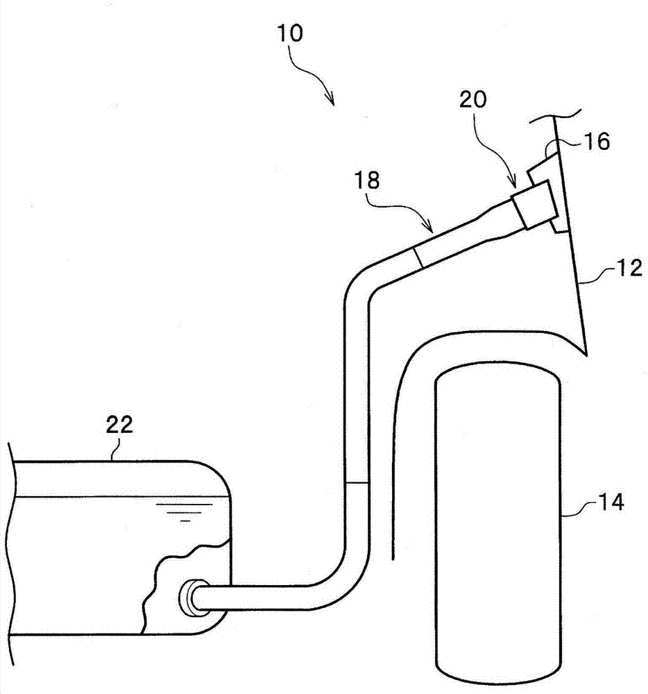
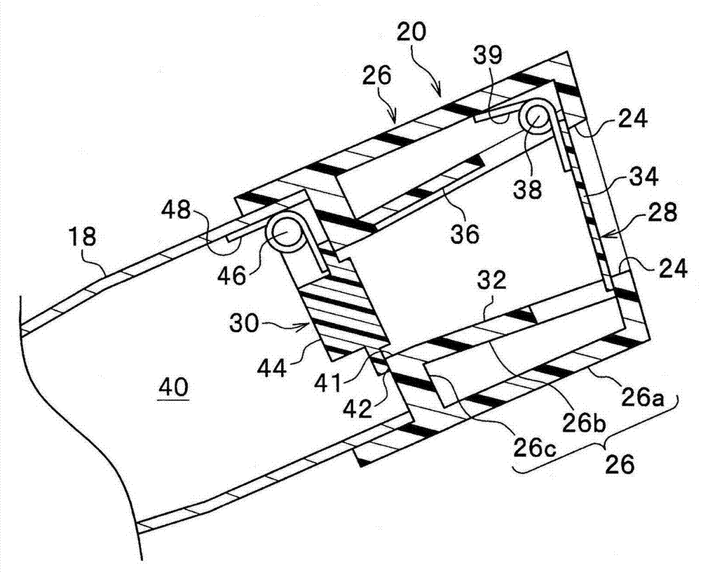
[0042] Next, embodiments of the present invention will be described in detail with reference to the drawings as appropriate. figure 1 It is a schematic block diagram of the refueling structure including the capless refueling mechanism into which the refueling auxiliary tool according to the embodiment of the present invention is inserted, viewed from the rear of the vehicle, figure 2 yes figure 1 An enlarged cross-sectional view of the capless refueling mechanism shown.

[0043] Such as figure 1 As shown, the refueling structure 10 is, for example, disposed on a rear fender 12 located at the rear of the vehicle body. An adapter 16 , which is positioned above the rear tire 14 and has an opening, is mounted on the inner side in the vehicle width direction of the rear fender 12 . On the side of the rear fender 12 facing the adapter 16 , a cover (not shown) is attached through a hinge so as to be openable and closable.

[0044] and, if figure 2 As shown, the refueling struc...


PUM


Abstract

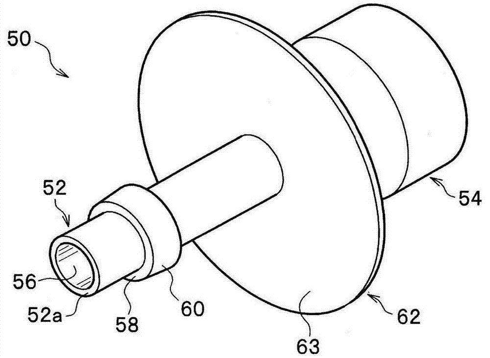
The invention provides a refueling auxiliary device which can restrain fuel vapour flowing back to the outside in a capless refueling mechanism. The capless refueling mechanism (20) includes a fill opening (24) side shut-off valve (28) disposed near the fill opening, and a fuel tank side shut-off valve (30) disposed nearer to a fuel tank than the fill opening side shut-off valve (28). The refueling auxiliary device (50) has a guide pipe section (52) and a funnel section (54), and pressing of the fill opening side shut-off valve (28) and the fuel tank side shut-off valve (30) via an end of the guide pipe section (52) causes a valve element (44) to be moved away from a seat portion (42) and insertion of a nozzle (64) into the funnel section (54) allows refueling. The outer circumferential surface of the guide pipe section (52) is provided with an enlarged diameter section (58) that regulates a valve opening degree of the valve element (44) of the fuel tank side shut-off valve (30).

Description

technical field [0001] The present invention relates to a fueling auxiliary tool used in a vehicle having a capless fueling mechanism at the front end of a fueling pipe. Background technique [0002] For example, Patent Document 1 discloses a capless refueling system that is arranged at the tip of a filler pipe and is snap-fitted by a valve assembly. It should be noted that "capless" means that there is no fuel cap conventionally provided at the fuel filler. [0003] This valve assembly includes a lower main body and an upper cover. A flapper valve biased by a spring into a seated state is disposed on the lower main body portion. Another flapper valve biased by a spring into a seated state is disposed on the upper cover. [0004] prior art literature [0005] patent documents [0006] Patent Document 1: Japanese PCT Publication No. 2013-509328 [0007] Summary of the invention [0008] The problem to be solved by the invention [0009] However, there is a case where ...

Claims


Application Information

Patent Timeline
Patent Type & Authority Applications(China)
IPC IPC(8): B60K15/077
CPCB67C11/02B60K15/04B60K2015/0429B60K2015/0461B67C2011/20B67D7/005B60K15/077
Inventor 荻原直贵坂口有亮土田真义
Owner HONDA MOTOR CO LTD
Learn More