Control device for internal combustion engine and control device for vehicle provided with said internal combustion engine
A technology for control devices and internal combustion engines, applied in mechanical control, engine control, fuel injection control, etc., to achieve the effect of suppressing engine oil loss
- Summary
- Abstract
- Description
- Claims
- Application Information
AI Technical Summary
Problems solved by technology
Method used
Image
Examples
Embodiment approach 1
[0071] [Description of system structure]
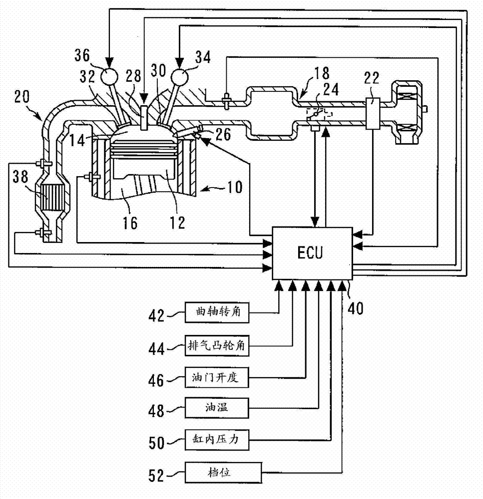
[0072] figure 1 It is a figure for demonstrating the system structure of the control apparatus of the vehicle equipped with the internal combustion engine which concerns on Embodiment 1 of this invention.
[0073] The system of this embodiment includes a spark ignition type internal combustion engine (gasoline engine) 10 . In the present embodiment, as an example, the internal combustion engine 10 is an inline four-cylinder engine having four cylinders #1 to #4.
[0074] A piston 12 is arranged in a cylinder of the internal combustion engine 10 . In the cylinder of the internal combustion engine 10 , a combustion chamber 14 is formed on the top side of the piston 12 , and a crankcase 16 is formed on the lower side of the piston 12 . An intake passage 18 and an exhaust passage 20 communicate with the combustion chamber 14 .
[0075] An air flow meter 22 that outputs a signal corresponding to the flow rate of air sucked into the int...
Embodiment approach 2
[0104] Second, refer to Figure 5 as well as Figure 6 Embodiment 2 of the present invention will be described.
[0105] use figure 1 shown in the hardware structure, by making the ECU 40 replace Figure 4 shown in the program while executing the following Figure 6 The program shown can realize the system of this embodiment.
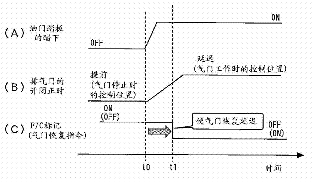
[0106] Figure 5 It is a time chart for explaining the characteristic control of Embodiment 2 of this invention. More specifically, Figure 5 (A) ~ (C) and image 3 (A) to (C) are similarly corresponding to the depression of the accelerator pedal, the control position of the opening and closing timing of the exhaust valve 32, and the F / C mark (valve return command), Figure 5 (D) shows a waveform showing a change in the peak value of the in-cylinder pressure (peak in-cylinder pressure) in one cycle of the internal combustion engine 10 .
[0107] Such as Figure 5 As shown in (A) and (B), when the depression of the accelerator pedal is detected...
Embodiment approach 3
[0117] Second, refer to Figure 7 as well as Figure 8 Embodiment 3 of the present invention will be described.
[0118] use figure 1 The hardware structure shown enables the ECU 40 to replace the Figure 4 shown in the program while executing the following Figure 8 The program shown in the figure realizes the system of this embodiment.
[0119] Figure 7 It is a time chart for explaining the characteristic control of Embodiment 3 of this invention. More specifically, Figure 7 (A) shows a waveform representing the actual gear position of the shift lever, Figure 7 (B) shows a waveform representing the detection information of the position sensor 52 , Figure 7 (C) shows a waveform indicating the control position of the opening and closing timing of the exhaust valve 32 . In addition, in Figure 7 In the situation shown, the accelerator pedal is not depressed (that is, the recovery request from the fuel stop is not issued).
[0120] As in Embodiments 1 and 2 descri...
PUM
 Abstract
Description
Claims
Application Information
 - R&D
- Intellectual Property
- Life Sciences
- Materials
- Tech Scout
- Unparalleled Data Quality
- Higher Quality Content
- 60% Fewer Hallucinations
Browse by: Latest US Patents, China's latest patents, Technical Efficacy Thesaurus, Application Domain, Technology Topic, Popular Technical Reports.
© 2025 PatSnap. All rights reserved.Legal|Privacy policy|Modern Slavery Act Transparency Statement|Sitemap|About US| Contact US: help@patsnap.com


