Panel joint structure

一种接合结构、面板的技术,应用在上部结构、上部结构分总成、上部结构分总成之间的连接等方向,能够解决接合部长度变短、接合强度变低等问题,达到提高可成形性、增强接合强度、增强放气效果的效果

Inactive Publication Date: 2016-03-30
TOYOTA JIDOSHA KK
View PDF7 Cites 5 Cited by
  • Summary
  • Abstract
  • Description
  • Claims
  • Application Information

AI Technical Summary

Problems solved by technology

However, in this case, the length of the joint portion where the pair of panels are joined to each other becomes short
For this reason, there is a concern that the joint strength between the pair of panels will become low

Method used


Image

  • Panel joint structure
  • Panel joint structure
  • Panel joint structure

Examples


Embodiment Construction

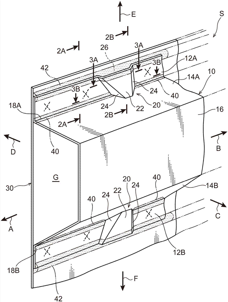
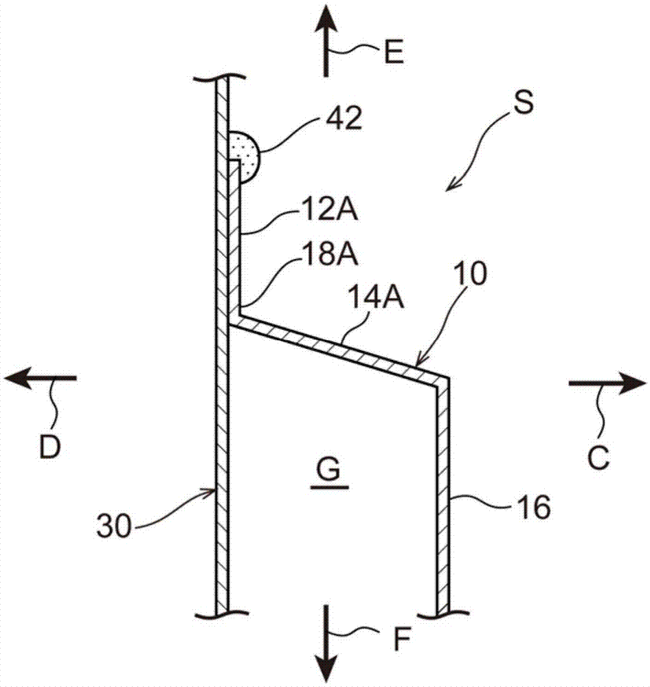
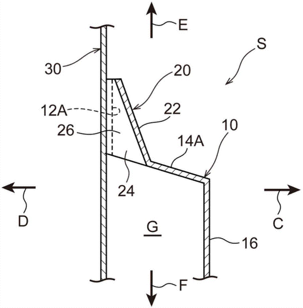
[0054] The panel joining structure S related to the embodiment of the present invention will be described below using the drawings. Such as figure 1 As shown in , the panel joint structure S is applied to the joint between the first panel 10 and the second panel 30 . In addition, the first panel 10 and the second panel 30 are members configuring the lower part of the vehicle (automobile). That is, for example, the first panel 10 is a skeleton member such as a cross member whose longitudinal direction coincides with the vehicle width direction of the vehicle, or a side member whose longitudinal direction coincides with the vehicle front-rear direction, and, for example, The second panel 30 is a floor panel configuring a floor of the vehicle. These will be specifically described below.

[0055] The first panel 10 is constructed of steel plate and along figure 1 The direction of the arrow A and the direction of the arrow B are formed in a substantially elongated shape. In ad...


PUM


Abstract

A panel joint structure including: a first panel; a second panel that forms a space between itself and the first panel; a joint portion; a seal member that seals a gap between a distal end portion of the joint flange portion and the second panel; and a first panel bead portion that is formed in a region of the joint flange portion adjacent to the joint portion in the lengthwise direction of the first panel, that projects in a direction away from the second panel, that extends from a distal end to a base end of the joint flange portion, that forms with the second panel an air vent hole communicated with the space, and that slopes in a direction away from the second panel heading toward the base end side of the joint flange portion as seen from the lengthwise direction of the first panel.

Description

technical field [0001] The present invention relates to a panel joining structure. Background technique [0002] Japanese Patent Application Laid-Open (JP-A) No. 2013-136076 discloses a panel joining structure in which a pair of panels each have a flange and the flanges are joined to each other. Further, a protrusion having a substantially semicircular cross section is formed in each of the paired flanges, and an air passage (air release hole) is formed by the paired protrusions. Thereby, when the pair of panels is subjected to electrodeposition coating in a state where the panels have been joined to each other, the air between the pair of panels can be released from the air passage. [0003] In addition, after electrodeposition coating of the panels, a sealing member is usually applied to the distal ends of the flanges thereby sealing the gap between the distal ends of the flanges, thereby preventing the inner sides of the pair of panels from becoming wet due to water. we...

Claims


Application Information

Patent Timeline
Patent Type & Authority Applications(China)
IPC IPC(8): B62D25/02B62D27/02
CPCB62D25/082B62D27/02B62D25/02B62D25/24
Inventor 小坂直哉
Owner TOYOTA JIDOSHA KK
Why Eureka
Try Eureka