Automatic production vibrating conveyer machine frame

A frame and component technology, applied in the direction of vibrating conveyors, conveyors, conveyor objects, etc., can solve the problems of easily damaged frame structure, frame tipping, poor shock absorption effect of the frame, etc., and achieve good stability , quality increase, good effect of shock absorption

Inactive Publication Date: 2016-03-30
黄丽
View PDF8 Cites 0 Cited by
  • Summary
  • Abstract
  • Description
  • Claims
  • Application Information

AI Technical Summary

Problems solved by technology

[0004] The existing frame is basically composed of columns, beams and longitudinal beams. Its main function is to support the vibrating device. However, since the vibrating device will generate frequent vibrations during operation, if the rack bracket is installed on the bottom surface and other supports, The shock absorption effect of the rack itself is poor, it is easy to damage the rack structure, and the damage to the support is also large.
In addition, if the height of the rack is high, when the vibration device is working, it is easy to cause the rack to tip over.

Method used


Image

  • Automatic production vibrating conveyer machine frame
  • Automatic production vibrating conveyer machine frame
  • Automatic production vibrating conveyer machine frame

Examples


Embodiment Construction

[0014] The present invention will be further described in detail below in conjunction with the accompanying drawings and specific embodiments.

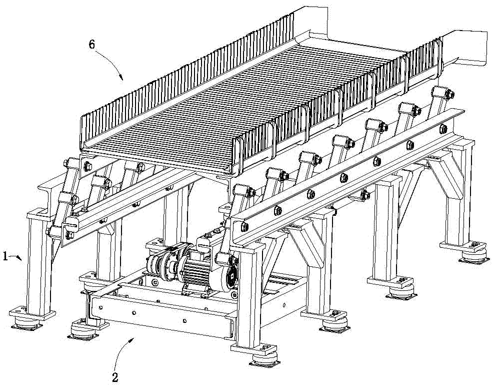
[0015] Such as Figure 1 to Figure 3 As shown, the vibrating conveyor for automatic production includes a frame 1 , a base 2 , a drive system 3 , a swing device 4 , a conveying support frame 5 and a conveying device 6 .

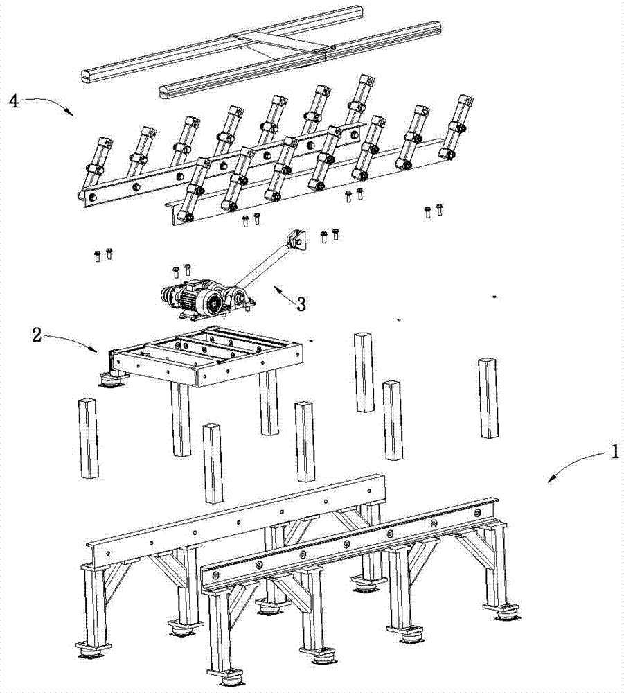
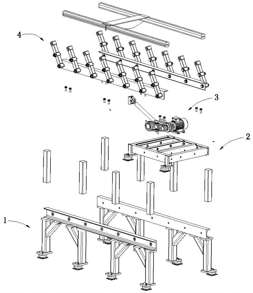
[0016] Such as Figure 1 to Figure 5 As shown, the automatic production vibrating conveyor frame 1 includes two symmetrically arranged frame components 100 . The frame assembly 100 includes more than two sets of support column assemblies and beams 10 . Each set of supporting column assemblies includes two symmetrically arranged supporting members 11 .

[0017] Such as Figure 4 and Figure 5 As shown, the support member 11 includes a frame shock absorber 111 , a column 112 , a diagonal brace 113 and a solid column 114 .

[0018] Such as Figure 4 , Figure 5 and Figure 6 As shown, the frame shock absorber 1...


PUM


Abstract

The invention discloses an automatic production vibrating conveyer machine frame. The automatic production vibrating conveyer machine frame comprises two machine frame components symmetrically arranged; each machine frame component comprises more than two sets of bearing post components and a cross beam; each set of the bearing post component comprises two bearing parts symmetrically arranged; each bearing part comprises a machine frame shock-absorbing seat, an stand column arranged on the machine frame shock-absorbing seat, a diagonal bracing column connected to the middle part of the stand column, and a solid column arranged inside the stand column; the stand column comprises a lower connecting plate, a stand column body and an upper connecting plate; the stand column body is connected between the lower connecting plate and the upper connecting plate; the cross beam is fixed on the bearing post components; and the stand column body adopts a hollow structure, the lower connecting plate and the upper connecting plate are welded to the two ends of the stand column body so as to seal the cavity inside the stand column body to form an airtight cavity, and the solid column is arranged in the airtight cavity. The automatic production vibrating conveyer machine frame provided by the invention has the advantages that the vibration reducing performance is improved, the bearing stability is improved, and the cost is lowered.

Description

technical field [0001] The invention relates to the automated production of vibrating conveyors, especially frames. Background technique [0002] At present, in order to realize continuous automatic production, conveyors are used in many places. The types of conveyors mainly include conveyor belt conveyors, conveyor roller conveyors and vibrating conveyors. The vibrating conveyor is a continuous conveying machine that uses a vibrator to vibrate the trough, so that the material in the trough slides or is thrown in a certain direction. [0003] Existing vibration conveyer mainly comprises frame, the vibrating device that is installed on the frame and is connected with vibrating device and is conveying device. [0004] The existing frame is basically composed of columns, beams and longitudinal beams. Its main function is to support the vibrating device. However, since the vibrating device will generate frequent vibrations during operation, if the rack bracket is installed on ...

Claims


Application Information

Patent Timeline
IPC IPC(8): B65G27/08B65G41/00
CPCB65G27/08B65G41/006
Inventor 黄丽
Owner 黄丽
Why Eureka
Try Eureka