Elution device and separation method for nitric acid type tin stripping waste liquid

A separation method and tin stripping technology, applied in chemical instruments and methods, metallurgical wastewater treatment, dehydration/drying/thickened sludge treatment, etc., can solve problems such as secondary pollution and low efficiency of distillation physical methods

Active Publication Date: 2018-01-19
JIANGSU WANHE COATING MACHINE CO LTD
View PDF2 Cites 0 Cited by
  • Summary
  • Abstract
  • Description
  • Claims
  • Application Information

AI Technical Summary

Problems solved by technology

These technologies provide a solution to certain aspects of resources recovered from waste tin stripping solutions. However, such as chemical methods and product transfer methods are likely to cause secondary pollution, and general electrolysis and distillation physical methods have low efficiency and other defects.

Method used


Image

  • Elution device and separation method for nitric acid type tin stripping waste liquid

Examples


Embodiment 1

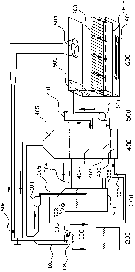
[0034] See figure 1 , A nitric acid type tin stripping waste liquid elution device includes a constant temperature condensation fractionator 100, a collection tank 200, a constant temperature distiller 300, an elution tank 400 and a dry fluidized bed 600.

[0035] The thermostatic distiller 300 is provided with an eluent inlet 303, a heater 301, a vapor outlet, and a liquid outlet 306 at the lower part.

[0036] The elution tank 400 is provided with a porous carrier plate 403. The porous carrier separates the interior of the elution tank 400 into a vapor buffer chamber 402 and an elution chamber 404. The vapor buffer chamber 402 is located at the lower part of the elution tank 400 and is connected to the thermostatic still 300. The elution chamber 404 is located above the porous carrier plate 403, the elution chamber 404 is provided with a waste liquid inlet 401, and the separation communication pipe 304 is provided between the elution chamber 404 and the thermostatic still 300, a...

Embodiment 2

[0055] The main technical solution of this embodiment is basically the same as that of Embodiment 1. For the features that are not explained in this embodiment, the explanation in Embodiment 1 is adopted, which will not be repeated here. A separation method of nitric acid type tin stripping waste liquid is as follows:

[0056] Open the injection port of the thermostatic distiller 300, fill the 200L thermostatic distiller 300 with ethanol eluent, and inject 100L of the nitric acid type tin stripping waste liquid into the sampling tube. The total tin content of the tin stripping waste liquid is 131.5g / L, Cu 2+ The concentration is 17.4g / L, start to heat the thermostatic still 300, control the temperature in the still to 85°C, so that ethanol vapor is injected into the elution tank 400 from the pipeline through the one-way valve piston 302, the hot vapor is the elution tank 400 After half an hour, the collection tank 200 began to produce droplets, and the liquid level of the connect...

Embodiment 3

[0059] The main technical solution of this embodiment is basically the same as that of Embodiment 1. For the features that are not explained in this embodiment, the explanation in Embodiment 1 is adopted, which will not be repeated here. A method for separating nitric acid type tin stripping waste liquid. In step (2), the temperature in the distiller is controlled to be 75°C, and the temperature of the lower part of the constant temperature condensation fractionator 100 is controlled to be 75°C.


PUM


Abstract

The invention discloses an eluting device for a nitric acid type tin-stripping waste liquid. The eluting device comprises a constant-temperature condensation fractionator, a collecting tank, a constant-temperature distiller, an eluting tank and a drying fluidized bed, wherein the constant-temperature distiller is provided with an eluent sample inlet, a heater and a steam outlet, the inside of the eluting tank is divided into a steam buffer chamber and an eluting chamber by a porous support, and the steam buffer chamber is formed in the lower part of the eluting tank and communicated with the steam outlet of the constant-temperature distiller; the eluting chamber is formed above the porous support, the lower part of the eluting chamber is communicated with the drying fluidized bed, and a gas outlet of the drying fluidized bed is communicated with the constant-temperature distiller; an exhaust chamber is communicated with the constant-temperature condensation fractionator which is communicated with the collecting tank. According to a separation method of the nitric acid type tin-stripping waste liquid, on the basis of the characteristic of immiscibility of ethanol and stannic acid, stannic acid, nitrate and a dilute nitric acid solution are separated in a sealed circulating elution system under the actions of eluting separation, evaporative crystallization, cooling fractionation and hot air drying, and meanwhile, recycling of an eluent, namely, ethanol, is guaranteed.

Description

Technical field [0001] The invention relates to the technical field of recovery of tin stripping waste liquid, in particular to an elution device and a separation method for nitric acid type tin stripping waste liquid. Background technique [0002] With the development of the PCB manufacturing industry, although new processes such as additive methods appear in the pattern transfer process, such as the use of conductive ink to print the pattern and then electroplating, the conductive ink used in this type of method requires the addition of a large amount of precious metals and can only be used in Printing on the substrate surface, the bonding force is not particularly high, the cost is high, the reliability is poor, and the hole copper processing is difficult. Therefore, the subtractive method is still the main method of graphics realization. When the circuit board design requires high-density wiring, small conductor spacing, back drilling, and alignment accuracy, it is generally ...

Claims


Application Information

Patent Timeline
Patent Type & Authority Patents(China)
IPC IPC(8): C02F1/04C02F1/02C02F11/16C23F1/46C02F101/20C02F103/16
CPCC02F1/02C02F1/04C02F11/16C02F2101/20C02F2103/16C23F1/46
Inventor 潘湛昌范红胡光辉肖楚民
Owner JIANGSU WANHE COATING MACHINE CO LTD
Why Eureka
Try Eureka