Mounting and manufacturing process of intelligent wireless communication equipment device

A technology of wireless communication equipment and manufacturing process, applied in the direction of reducing energy consumption, sustainable communication technology, advanced technology, etc., can solve the problems of increasing the speed of rapid temperature diffusion, inconsistent structural characteristics of heat sinks, slow processing efficiency, etc. The effect of surface burrs, improving production quality and improving processing efficiency

Active Publication Date: 2021-12-17
宜宾市天珑通讯有限公司
View PDF5 Cites 0 Cited by
  • Summary
  • Abstract
  • Description
  • Claims
  • Application Information

AI Technical Summary

Problems solved by technology

[0004] Aiming at the problems in the prior art, the purpose of the present invention is to provide a device installation and manufacturing process for intelligent wireless communication equipment, which solves the existing problem. In order to improve the heat dissipation effect, several equal-spaced distribution holes are often provided on the outer surface of the heat dissipation cylinder. The heat sink, through the gap inside the heat sink, increases the rapid diffusion speed of the temperature, and for the production of the heat sink on the outer surface of the heat sink, in the prior art, cutting or hobbing is often used to realize the production of the heat sink , such a processing method has technical problems such as slow processing efficiency and inconsistent structural features of the heat sink

Method used


Image

  • Mounting and manufacturing process of intelligent wireless communication equipment device
  • Mounting and manufacturing process of intelligent wireless communication equipment device
  • Mounting and manufacturing process of intelligent wireless communication equipment device

Examples


Embodiment Construction

[0062] In order to make the technical means, creative features, goals and effects achieved by the present invention easy to understand, the present invention will be further elaborated below in conjunction with specific drawings. It should be noted that, in the case of no conflict, the embodiments and Features in the embodiments can be combined with each other.

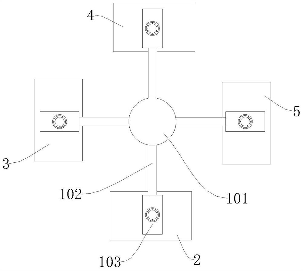
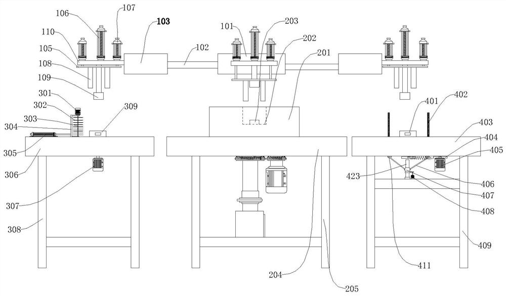
[0063] see Figure 1-16 It is a schematic diagram of the overall structure of an intelligent wireless communication device device installation and manufacturing process;

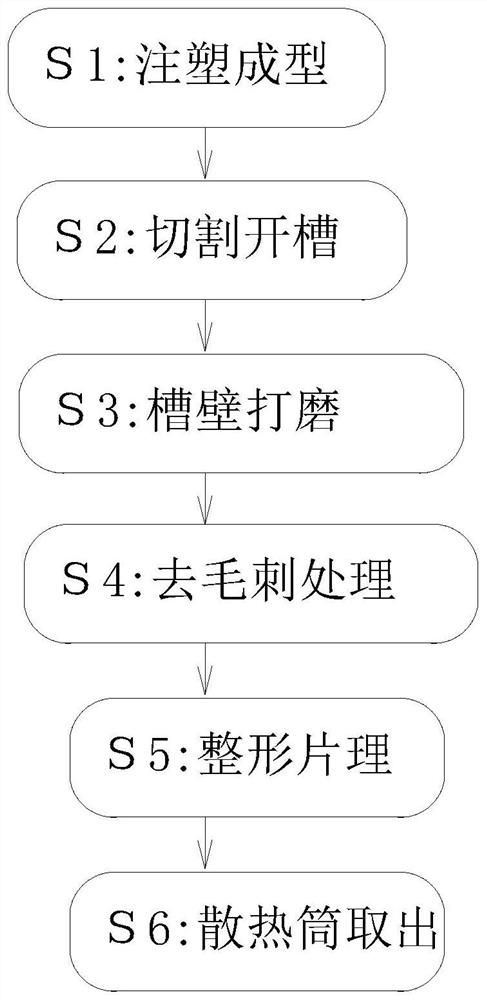
[0064] A manufacturing process for installing components of an intelligent wireless communication device, comprising the following steps:

[0065] S1. Injection molding: Put the mixed copper liquid into the molding cavity, squeeze the copper liquid in the molding cavity and keep it for a period of time, so that the copper liquid is cooled and formed in the molding cavity, and then it is taken out to obtain the injection molding. radiator;

[0066...


PUM


Abstract

The invention provides a mounting and manufacturing process of an intelligent wireless communication equipment device, and relates to the technical field of intelligent wireless communication equipment production. The mounting and manufacturing process of the intelligent wireless communication equipment device comprises the following steps of S1, injection molding, specifically, putting a mixed copper liquid into a molding cavity, extruding the copper liquid in the molding cavity and keeping for a period of time, cooling and molding the copper liquid in the molding cavity, and taking out the copper liquid to obtain the injection-molded heat dissipation cylinder; and S2, cutting and grooving, specifically, conducting cutting and grooving on the surface of the heat dissipation cylinder subjected to injection molding in the step S1. According to the mounting and manufacturing process, through the machining procedures completed in sequence, the production quality of a heat dissipation device can be effectively improved, burrs on the surface of the formed heat dissipation device can be reduced, particularly, the effective removal rate of the burrs on the edge of a grooved heat dissipation blade can reach 90% or above, through rapid reversing of a steering assembly, whole-process machining is achieved without manual operation, the production and machining safety is improved, and the machining efficiency of the heat dissipation device is improved.

Description

technical field [0001] The invention relates to the technical field of production of intelligent wireless communication equipment, in particular to a process for installing and manufacturing components of intelligent wireless communication equipment. Background technique [0002] Communication equipment, referred to as ICD in English, is used for wired communication equipment and wireless communication equipment in industrial control environments. Wireless communication equipment mainly includes wireless APs, wireless bridges, wireless network cards, wireless lightning arresters, wireless cameras, antennas, mobile phones, computers and other electronic equipment. [0003] When any kind of wireless communication equipment is working, the components will generate heat, which requires the application of heat dissipation devices to dissipate heat from electronic components. Common heat dissipation devices include heat pipes, cooling fans, and heat sinks specially designed for spe...

Claims


Application Information

Patent Timeline
IPC IPC(8): B23P15/00
CPCB23P15/00Y02D30/70
Inventor 李国龙
Owner 宜宾市天珑通讯有限公司
Why Eureka
Try Eureka