Direct-heating waste heat recovery system of centrifugal type and oil-free screw type compressors

A waste heat recovery system and waste heat recovery technology, applied in lighting and heating equipment, heat exchanger types, indirect heat exchangers, etc., can solve the problem of shortened service life of heat exchangers, inability to perform complete heat exchange, and reduced heat exchange efficiency, etc. problem, to achieve the effect of prolonging the service life, not easy to scale, sufficient and uniform heat exchange

Active Publication Date: 2016-03-30
GUANGDONG SHUNDE HYNOV HEAT TECH CO LTD
View PDF13 Cites 5 Cited by
  • Summary
  • Abstract
  • Description
  • Claims
  • Application Information

AI Technical Summary

Problems solved by technology

The problems of the two are: first, the heat transfer coefficient of the gas shell side is low, the volume is too large, and it is easy to cause space restrictions and cannot be installed
The heat exchanger with the above-mentioned structure has the following defects: 1. The water at the inner wall of the baffle plate and the main body of the shell easily forms a vortex zone, which is easy to generate scale
2. There is a certain gap between the heat transfer tube and the baffle, and there is a certain gap between the baffle and the shell body, which is easy to cause short flow and reduce the heat exchange efficiency, especially when using direct heat exchange, due to the shell side The flow rate is too small, and the short flow is serious and cannot perform complete heat exchange
3. The cross-flow mode of compressed air flowing horizontally and water flowing vertically, compared with the pure counter-flow mode, the heat transfer efficiency is lower
4. It is difficult to clean the scale blocked in the main body of the horizontal tube shell, which not only affects the efficiency of use, but also shortens the service life of the entire heat exchanger

Method used


Image

  • Direct-heating waste heat recovery system of centrifugal type and oil-free screw type compressors
  • Direct-heating waste heat recovery system of centrifugal type and oil-free screw type compressors
  • Direct-heating waste heat recovery system of centrifugal type and oil-free screw type compressors

Examples


Embodiment 1

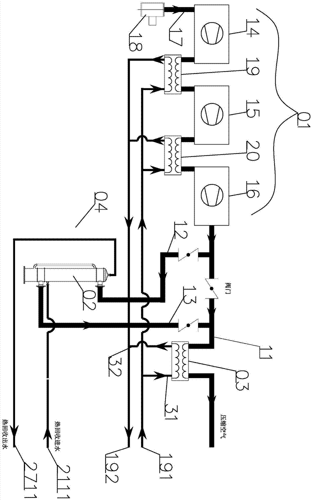
[0023] The direct heating type of embodiment 1 is that no secondary heat exchanger, internal circulation water pump and expansion tank are installed.

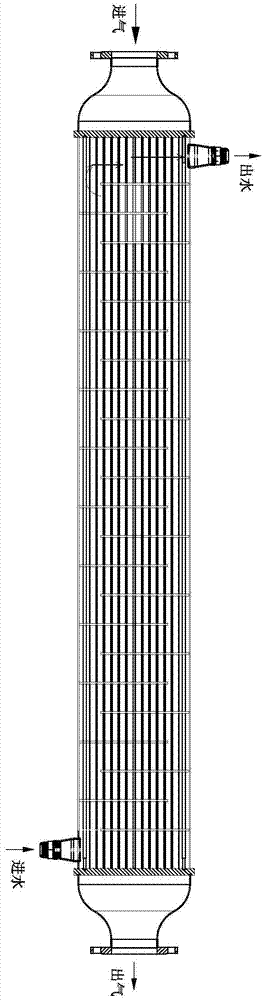
[0024] Such as figure 2As shown, the direct heat waste heat recovery system of centrifugal and oil-free screw air compressors includes air compressor 01, waste heat recovery device 02 connected to the pipe body of air compressor The stage cooler 03, and the heat recovery water pipe body 04 connected with the waste heat recovery device 02 pipe body. The waste heat recovery device 02 is a vertically installed waste heat recovery device 02 . The waste heat recovery device 02 includes a vertical tube shell main body 21, a plurality of equal-length inner heat transfer tubes 22 are arranged inside the vertical tube shell main body 21, and the inner heat transfer tubes 22 are jacketed with a length corresponding to the length of the inner heat transfer tubes 22. The outer heat transfer sleeve 23, the first tube plate 24 for fixing ...

Embodiment 2 2

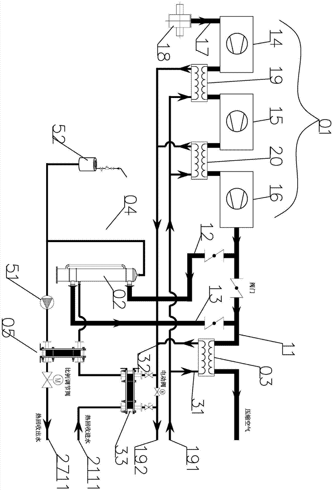
[0026] Embodiment 2 The secondary exchange type is that a secondary heat exchanger, an internal circulation water pump and an expansion tank are installed.

[0027] Such as image 3 As shown, the direct heat waste heat recovery system of centrifugal and oil-free screw air compressors includes air compressor 01, waste heat recovery device 02 connected to the pipe body of air compressor The stage cooler 03, and the heat recovery water pipe body 04 connected with the waste heat recovery device 02 pipe body. The waste heat recovery device 02 is a vertically installed waste heat recovery device 02 . The waste heat recovery device 02 includes a vertical tube shell main body 21, a plurality of equal-length inner heat transfer tubes 22 are arranged inside the vertical tube shell main body 21, and the inner heat transfer tubes 22 are jacketed with a length corresponding to the length of the inner heat transfer tubes 22. The outer heat transfer sleeve 23, the first tube plate 24 for f...

Embodiment 3

[0029] Embodiment 3 The embodiment of centrifugal air compressor:

[0030] According to the same principle, the waste heat of the high-temperature compressed gas generated at each stage of the compressor can be recovered. The high-temperature compressed gas enters the air storage chamber 25 from the inlet pipe port 251, and then the compressed air flows from the interlayer between the inner heat transfer tube 22 and the outer heat transfer sleeve 23 to the outlet air storage chamber 26 at the other end. The compressed air is discharged from the outlet pipe port 261 .

[0031]If the direct heating structure is adopted, after the water enters through the water inlet pipe 211, it directly exchanges heat with the waste heat recovery device 03 . In this way, the hot water enters the inside of the vertical shell main body 21 and exchanges heat with the outer surface of the outer heat transfer sleeve 23 . When the hot water rises to the external connecting pipe 272 on the main body...


PUM


Abstract

The invention discloses a waste heat recovery system of centrifugal type and oil-free screw type compressors. The system comprises an air compressor, a waste heat recovery device, a final-stage cooler and a heat recovery water pipe body, wherein the waste heat recovery device is a vertically mounted waste heat recovery device and comprises a vertical tube shell main body, inner heat transfer tubes, an outer heat transfer sleeve, first tube plates, an air inlet accommodating chamber and an air outlet settling chamber. The system has the effects of full and uniform heat exchange, small size, flexibility in mounting and using, durable structure, low possibility of scale deposition on the surface of the heat transfer tubes, convenience in cleaning and high recovery efficiency of the compressor.

Description

technical field [0001] The invention belongs to the field of waste heat recovery equipment, in particular to a direct heat waste heat recovery system of centrifugal and oil-free screw air compressors. Background technique [0002] There are usually two types of waste heat recovery heat exchangers for centrifugal air compressors and oil-free screw air compressors, one of which is the gas going through the shell side, and the other is the gas going through the pipe, such as figure 1 shown. The problems of the two are as follows: first, the heat transfer coefficient of the gas going through the shell is low, and the volume is too large, which may easily cause space restrictions and cannot be installed. Second, the structure of the gas tube path is mainly composed of a horizontal tube shell main body, a plurality of heat transfer tubes leading to high-temperature compressed air in the horizontal tube shell main body, and dislocation distribution tubes in the horizontal tube she...

Claims


Application Information

Patent Timeline
Patent Type & Authority Applications(China)
IPC IPC(8): F28D7/00
CPCF28D7/00
Inventor 黄华杰
Owner GUANGDONG SHUNDE HYNOV HEAT TECH CO LTD
Why Eureka
Try Eureka