Damping device

A technology of damping device and pressure relief device, which is applied in the direction of emergency protection device, shock absorber, electrical components, etc., can solve the problems affecting closing performance, etc., and achieve the effect of improving dynamic performance and avoiding rebound

Inactive Publication Date: 2016-03-30
陈鸽
View PDF5 Cites 3 Cited by
  • Summary
  • Abstract
  • Description
  • Claims
  • Application Information

AI Technical Summary

Problems solved by technology

The dynamic performance of opening and closing of high and low voltage circuit breakers with damping devices and energy storage devices has been greatly improved. However, when closing, the damping

Method used


Image

  • Damping device
  • Damping device
  • Damping device

Examples


Embodiment approach 1

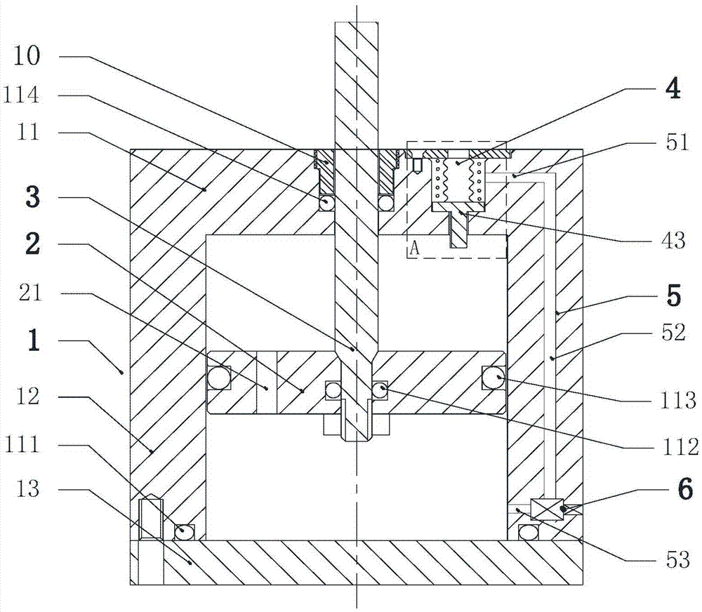
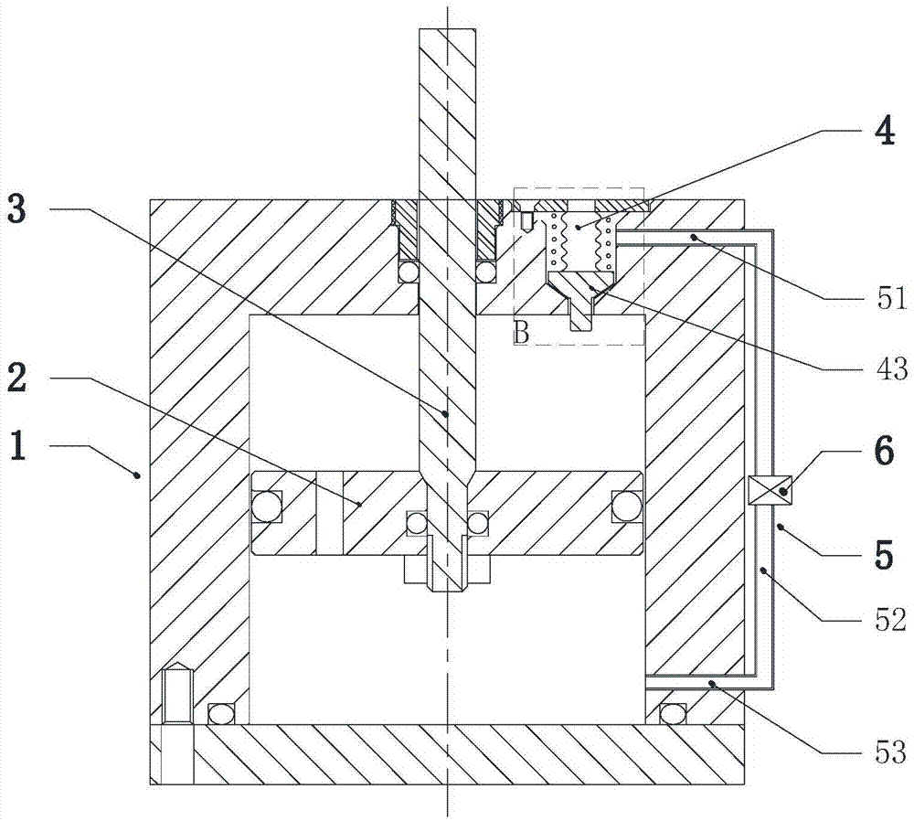
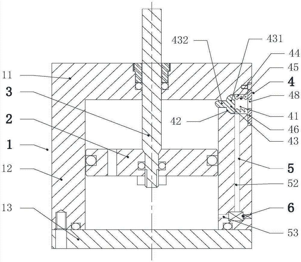
[0056] In a damping device of the present invention, the pressure relief device 4 is arranged on the end cover of the cylinder body 1 . The damping device, such as figure 1As shown, it includes a cylinder 1, a piston 2, a piston rod 3, a pressure relief device 4, a channel 5 and a regulating valve 6. The cylinder body 1 includes a first end cover 11 , a cylinder barrel 12 and a second end cover 13 . The first end cover 11 is sealed and fixed to the top end of the cylinder barrel 1 . To facilitate the manufacture of the channel 5 and the sealing communication, the first end cover 11 and the cylinder barrel 12 are integrally formed. The second end cover 13 is fixed on the bottom end of the cylinder barrel 12 by bolts, and the second end cover 13 and the bottom end of the cylinder barrel 12 are sealed by the first sealing ring 111 . The piston 2 is arranged inside the cylinder 1, and the side surface of the piston 2 and the inner surface of the cylinder 12 are sealed by the thi...

Embodiment approach 2

[0075] A circuit breaker of the present invention, such as Figure 12 As shown, it consists of three unipolar switches 20 and a control circuit. Wherein, the control circuit is the prior art, which is not the protected technical point of the present invention, and will not be described in detail here; the structures of the three unipolar switches 20 are all the same, and one of the unipolar switches 20 will be described below. The single-pole switch 20 includes a vacuum bubble 201 , an insulating cylinder 202 , and an electromagnetic driver 203 , and the insulating cylinder 202 has a built-in energy storage device 205 . The energy storage device 205 includes a cylinder 206 , a piston 207 , a piston rod 208 and a spring 209 arranged in the insulating cylinder 202 . The cylinder body 206 of the insulating cylinder 202 is a closed body composed of the bottom end cover 2063, the cylinder tube 2062 and the top end cover 2061. The lower end of the cylinder tube 2062 is fixed on the...


PUM


Abstract

The invention discloses a damping device and a breaker. The damping device comprises a cylinder body, a piston, a piston rod, a channel and a pressure relief device, wherein the cylinder body comprises a first end cover, a cylinder barrel and a second end cover; one end part of the piston rod runs through the first end cover, extends into the cylinder body, and is fixed to the piston in the cylinder body; the piston partitions the cylinder body into a first chamber located at the side of the first end cover and a second chamber; the pressure relief device is assembled on the cylinder body; a valve rod part of a built-in pressure relief valve core of the pressure relief device extends towards the first chamber; the breaker comprises a single-pole switch; the single-pole switch is axially connected with the damping device; the damping device decompresses and relieves damping at the end of the stroke of a vacuum bubble moving contact when closed; damping force is prevented from promoting a closing bounce of the moving contact of the breaker; and the closing performance is improved. The pressure relief device is arranged on the cylinder body of the damping device, so that installation and maintenance of the pressure relief device and change of the pressure relief valve core are facilitated.

Description

technical field [0001] The invention relates to a damping device, in particular to a damping device that generates damping at the front end of the stroke and releases damping at the end of the stroke and is easy to maintain, and a circuit breaker using the damping device, belonging to the field of electric equipment. Background technique [0002] After the circuit breaker is opened, the speed of the moving contact of the vacuum bubble is still high when it moves to the end of its stroke. The moving contact collides with the limit piece and rebounds. When the distance between the moving contact and the static contact is less than the discharge When the critical distance is reached, discharge occurs and arcing occurs. For the opening rebound of the moving contact, a damping device is often used to consume the energy of the moving contact and prevent it from rebounding after opening. When closing, the high-speed moving moving contact in the vacuum bubble collides with the stat...

Claims


Application Information

Patent Timeline
IPC IPC(8): H01H71/50F16F9/19F16F9/34F16F9/49
CPCH01H71/504F16F9/19F16F9/34F16F9/49
Inventor 陈鸽
Owner 陈鸽
Why Eureka
Try Eureka