Feedback control method and circuit of switching power supply

A feedback control, switching power supply technology, used in control/regulation systems, high-efficiency power electronic conversion, electrical components, etc., can solve problems such as insufficient steady-state performance, insufficient load regulation, large low-frequency ripple, etc., to improve The effect of load regulation, volume reduction, and low frequency ripple reduction

Active Publication Date: 2016-03-30
MORNSUN GUANGZHOU SCI & TECH
View PDF8 Cites 15 Cited by
  • Summary
  • Abstract
  • Description
  • Claims
  • Application Information

AI Technical Summary

Problems solved by technology

[0004] However, although the dynamic performance of the cross-cycle modulation adopted by CN201410085973 is superior, the st

Method used


Image

  • Feedback control method and circuit of switching power supply
  • Feedback control method and circuit of switching power supply
  • Feedback control method and circuit of switching power supply

Examples


Embodiment 1

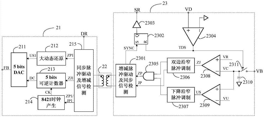
[0037] A new type of feedback control circuit, such as figure 2 As shown, it includes a primary side modulation and demodulation circuit 21 , a magnetic isolation transformer 22 and a secondary side modulation and demodulation circuit 23 connected in sequence. The primary side modulation and demodulation circuit 21 modulates the falling edge of the main power tube drive signal into a synchronous narrow pulse, which is transmitted to the secondary side modulation and demodulation circuit 23 through the magnetic isolation transformer 22, and the secondary side modulation and demodulation circuit 23 detects the synchronous narrow pulse to synchronize The rectifier is turned on; the secondary modulation and demodulation circuit 23 also detects the drain voltage of the synchronous rectifier, and the synchronous rectifier is turned off; when the synchronous rectifier is turned off, the divided voltage value of the output voltage is sampled, and the sampled divided The voltage value...

Embodiment 2

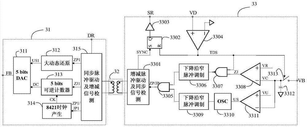
[0048] The feedback control circuit of the second embodiment is as image 3 As shown, it includes a primary side modulation and demodulation circuit 31 , a magnetic isolation transformer 32 and a secondary side modulation and demodulation circuit 33 connected in sequence.

[0049] The circuit modules included in the main-side modulation and demodulation circuit 31 and their connection relationship are the same as those of the main-side modulation and demodulation circuit 21 in Embodiment 1, and will not be repeated here.

[0050]The secondary side modulation and demodulation circuit 33 further includes: a second falling edge narrow pulse modulation circuit 3306 , a NAND gate 3307 , and an oscillator (OSC) 3310 on the basis of the secondary side modulation and demodulation circuit 23 in Embodiment 1. The difference between the second embodiment and the first embodiment is that the second falling edge narrow pulse modulation circuit 3306 replaces the function of the double edge ...


PUM


Abstract

The invention provides a novel and reliable feedback control circuit. A feedback signal is discretized and modulated into narrow pulse, the narrow pulse is fed back to the primary side of an isolation power supply, and a primary side circuit detects the narrow pulse to generate a proper feedback signal used for the closed loop control of a PWM (Pulse-Width Modulation)/PFM (Pulse Frequency Modulation) master control circuit. The novel and reliable feedback control circuit has the beneficial effects that secondary side feedback and master side control under magnetic isolation are realized. Compared with a modulation way of PSM (Pulse cycle Skip Modulation), the novel and reliable feedback control circuit improves steady-state performance under a condition that the dynamic performance of the power supply is not lowered, lowers low-frequency ripple, improves a load regulation rate, reduces the volume of a magnetic isolation transformer and simplifies a feedback process while the volume of the magnetic isolation transformer is reduced and power consumption is lowered. Since a master side control synchronous rectifier is opened, convenience is brought for realizing synchronous rectification and improving reliability. At the finishing moment of the synchronous rectification, output voltage is sampled, and sampling precision is improved.

Description

technical field [0001] The invention relates to a switching power supply, in particular to a reliable and low power consumption feedback control method and circuit for realizing closed-loop control of the switching power supply. Background technique [0002] Switching power supplies are widely used in industrial fields due to their high efficiency and the ability to realize buck-boost and other advantages. All switching power supplies need to detect the output voltage or current information, and feed it back to the control circuit to control the on-off of the power tube and realize the energy transfer. The feedback path is divided into isolated type and non-isolated type according to whether there are safety regulations. The isolated type feedback uses an isolation device to disconnect the feedback path to meet safety regulations. Commonly used isolation methods for isolated feedback include magnetic isolation, optocoupler isolation, and capacitive isolation. Among them, t...

Claims


Application Information

Patent Timeline
IPC IPC(8): H02M3/28H02M3/335
CPCH02M3/28H02M3/335H02M1/0006Y02B70/10
Inventor 於昌虎唐盛斌曾正球
Owner MORNSUN GUANGZHOU SCI & TECH
Why Eureka
Try Eureka