Linear constant current circuit

A linear constant current circuit and circuit load technology, applied in electrical components, regulating electrical variables, converting DC power input to DC power output, etc. ripple effect

Active Publication Date: 2020-04-28
ON BRIGHT ELECTRONICS SHANGHAI
View PDF4 Cites 0 Cited by
  • Summary
  • Abstract
  • Description
  • Claims
  • Application Information

AI Technical Summary

Problems solved by technology

[0006] In some application scenarios, the low-frequency ripple of the output current Io is required to be as small as possible, which requires a larger capacity of the output capacitor Co, but the output capacitor Co is generally an electrolytic capacitor, and the larger the capacity, the larger the volume. This prevents miniaturization of the power supply volume

Method used


Image

  • Linear constant current circuit
  • Linear constant current circuit
  • Linear constant current circuit

Examples


Embodiment Construction

[0021] Features and exemplary embodiments of various aspects of the invention will be described in detail below. In the following detailed description, numerous specific details are set forth in order to provide a thorough understanding of the present invention. It will be apparent, however, to one skilled in the art that the present invention may be practiced without some of these specific details. The following description of the embodiments is only to provide a better understanding of the present invention by showing examples of the present invention. The present invention is by no means limited to any specific configuration presented below, but covers any modification, substitution and improvement of elements, components and algorithms without departing from the spirit of the invention. In the drawings and the following description, well-known structures and techniques have not been shown in order to avoid unnecessarily obscuring the present invention.
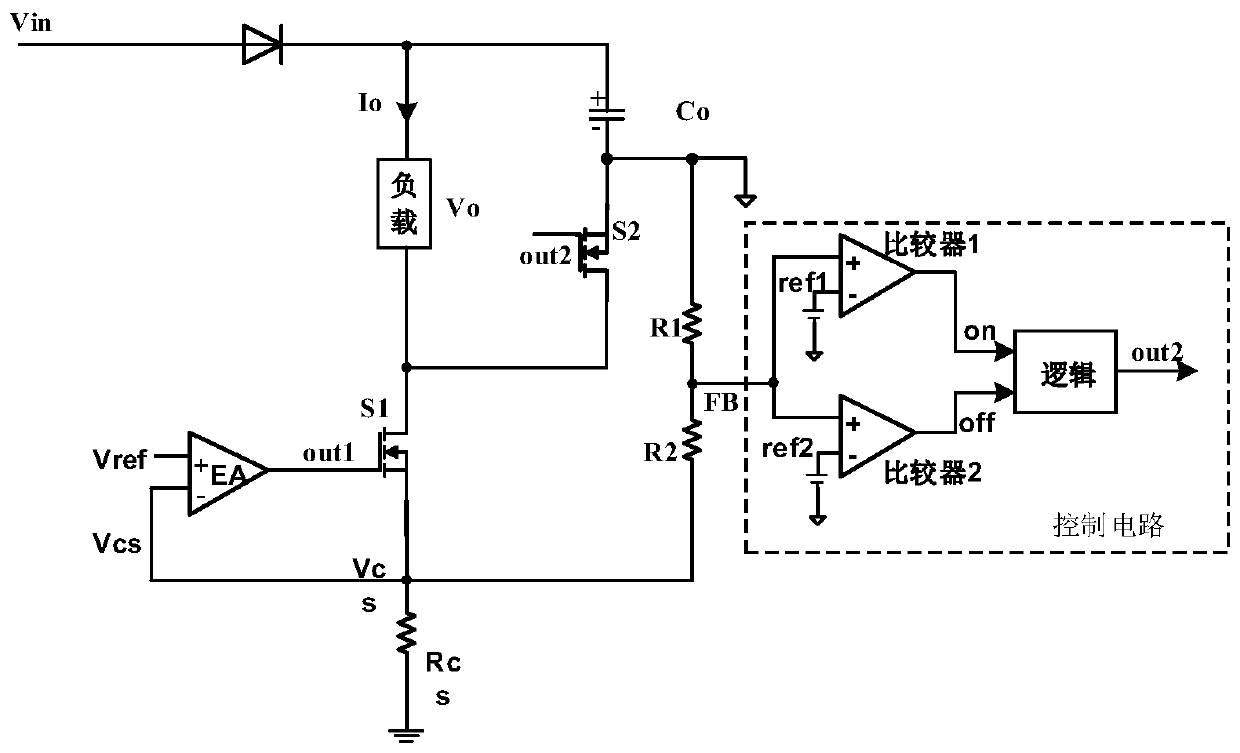
[0022] image 3...


PUM


Abstract

Disclosed is a linear constant current circuit, comprising first and second power switches, an output capacitor, a current sampling resistor, an operational amplifier, and a control circuit for a second power switch, wherein: the positive terminal of the output capacitor is connected to the positive voltage of the circuit load The drain of the first power switch is connected to the negative voltage terminal of the circuit load, the source of the first power switch is connected to the system ground through the current sampling resistor, and the gate of the first power switch is connected to the output terminal of the operational amplifier. The drain of the second power switch is connected to the drain of the first power switch, the source of the second power switch is connected to the negative terminal of the output capacitor as the reference ground of the control circuit, and the gate of the second power switch is connected to the negative terminal of the control circuit. The output terminal is connected, and the control circuit generates a second switch control signal for controlling the turn-on and turn-off of the second power switch based on the output characterization voltage representing the output voltage at both ends of the circuit load or the output capacitor, the second and the third reference voltage .

Description

technical field [0001] The invention relates to the field of circuits, in particular to a linear constant current circuit. Background technique [0002] figure 1 The working principle diagram of the traditional linear constant current circuit is shown. exist figure 1 In the linear constant current circuit shown, the positive terminal and negative terminal of the output capacitor Co are respectively connected to both ends of the load; the drain of the power switch S1 is connected to the negative terminal of the output capacitor Co; the source of the power switch S1 is sampled through the current The resistor Rcs is connected to the system ground; the gate of the power switch S1 is connected to the output terminal of the operational amplifier (EA), wherein: the current sampling resistor Rcs samples the output current Io flowing through the load to generate a current sampling voltage Vcs; the operational amplifier (EA) ) Based on the current sampling voltage Vcs and the refe...

Claims


Application Information

Patent Timeline
Patent Type & Authority Patents(China)
IPC IPC(8): H02M3/158H02M1/08H02M1/14
CPCH02M1/08H02M1/14H02M3/158H02M1/0006H02M1/0045
Inventor 方倩周俊
Owner ON BRIGHT ELECTRONICS SHANGHAI
Why Eureka
Try Eureka