LED driver for chopping light adjustment occasion

An LED driver and dimmer technology, applied in the field of chopper dimming, can solve the problems of loss, low overall efficiency of the LED driver, affecting the startup speed of the DC-DC control unit 40, etc., so as to solve the impedance matching problem and avoid loss. Effect

Active Publication Date: 2016-03-30
INVENTRONICS HANGZHOU
View PDF5 Cites 1 Cited by
  • Summary
  • Abstract
  • Description
  • Claims
  • Application Information

AI Technical Summary

Problems solved by technology

[0004] It can be seen that after the DC-DC control unit 40 is started, the energy of the auxiliary source circuit 30 can be independently provided by the power supply VC, and the start-up resistor R1 does not need to exist at this time, and if R1 is still connected at the original position, unnecessary losses, resulting in lower overall efficiency of the LED driver
And if the loss caused by R1 is reduced by increasing the resistance value of the starting resistor R1, it will affect the starting speed of the DC-DC control unit 40

Method used


Image

  • LED driver for chopping light adjustment occasion
  • LED driver for chopping light adjustment occasion
  • LED driver for chopping light adjustment occasion

Examples


Embodiment Construction

[0028] The following will clearly and completely describe the technical solutions in the embodiments of the present invention with reference to the accompanying drawings in the embodiments of the present invention. Obviously, the described embodiments are only some, not all, embodiments of the present invention. Based on the embodiments of the present invention, all other embodiments obtained by persons of ordinary skill in the art without making creative efforts belong to the protection scope of the present invention.

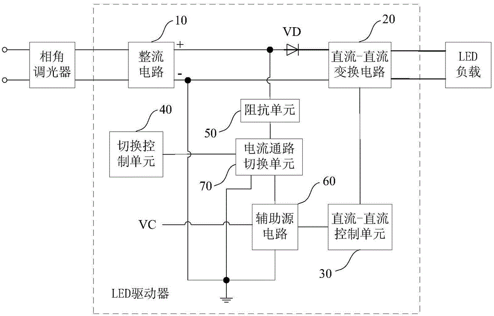
[0029] see figure 2 , the embodiment of the present invention discloses an LED driver applied to chopper dimming occasions to reduce the power loss of the LED driver, including a rectifier circuit 10, a DC-DC conversion circuit 20, a DC-DC control unit 30, and a switching control unit 40 and the current path, wherein:

[0030] The rectifier circuit 10 and the DC-DC conversion circuit 20 are sequentially connected between the phase angle dimmer and the LED lo...


PUM


Abstract

The embodiment of the invention discloses an LED driver for a chopping light adjustment occasion, and the driver comprises a rectification circuit and a DC-DC conversion circuit, wherein the rectification circuit and the DC-DC conversion circuit are sequentially connected between a phase angle light modulator and an LED load; and a current circuit which is in parallel connection with an output side of the rectification circuit, wherein the current circuit comprises an impedance circuit, an auxiliary source circuit, and a current circuit switching unit. A first end of the current circuit switching unit is connected with a first output end of the rectification circuit through the impedance circuit, a second end of the current circuit switching unit is connected with a second output end of the rectification circuit, and a third end of the current circuit switching unit is connected with the second output end of the rectification circuit through the auxiliary source circuit. The driver also comprises a DC-DC control unit which is connected with the auxiliary source circuit and the DC-DC conversion circuit; and a switching control unit which is connected with the current circuit switching unit and is used for controlling the connection from the first end of the current circuit switching unit to the second end or the third end according to a preset rule, so as to reduce the power loss of the driver.

Description

technical field [0001] The present invention relates to the technical field of chopping and dimming, and more specifically, relates to an LED driver applied to the occasion of chopping and dimming. Background technique [0002] In the case of chopper dimming, the chopper voltage output by the phase angle dimmer is transmitted to the LED (Light Emitting Diode, light emitting diode) load after passing through the LED driver, and the LED can be changed by adjusting the conduction phase angle of the chopper voltage. The size of the driving current, and then change the brightness of the LED load. [0003] see figure 1 , the LED driver includes: a rectifier circuit 10 and a DC-DC conversion circuit 20 connected in turn between the phase angle dimmer and the LED load, and a series branch connected in parallel to the output side of the rectifier circuit 10 (including a series startup resistor R1 and the auxiliary source circuit 30), and the DC-DC control unit 40 connecting the aux...

Claims


Application Information

Patent Timeline
Patent Type & Authority Applications(China)
IPC IPC(8): H05B37/02
Inventor 罗世伟俞杭冬
Owner INVENTRONICS HANGZHOU
Why Eureka
Try Eureka