Clamping table for machining slanting tee joint valves

An oblique tee and clamping table technology, applied in metal processing equipment, metal processing mechanical parts, clamping and other directions, can solve the problems of high production and processing costs, waste of resources, and high cost input, and achieve low production and manufacturing costs. Easy to use, reasonable structure design effect

Inactive Publication Date: 2016-04-06
WUHU JIENUO TECH
View PDF7 Cites 2 Cited by
  • Summary
  • Abstract
  • Description
  • Claims
  • Application Information

AI Technical Summary

Problems solved by technology

[0002] As we all know, in the process of valve production and processing, different types of valves require special fixtures for positioning, which makes the cost of production and processing higher, especially for inclined three-way valves, because the slope of each type of inclined three-way valves is different. Not the same, the design of this fixture brings difficulty. If each fixture is designed with a separate fixture, the production and processing costs of the product will be high, and the discarded fixtures will not be recycled, resulting in serious waste of resources.

Method used


Image

  • Clamping table for machining slanting tee joint valves
  • Clamping table for machining slanting tee joint valves
  • Clamping table for machining slanting tee joint valves

Examples


Embodiment Construction

[0013] In order to make the technical means, creative features, goals and effects achieved by the present invention easy to understand, the present invention will be further elaborated below.

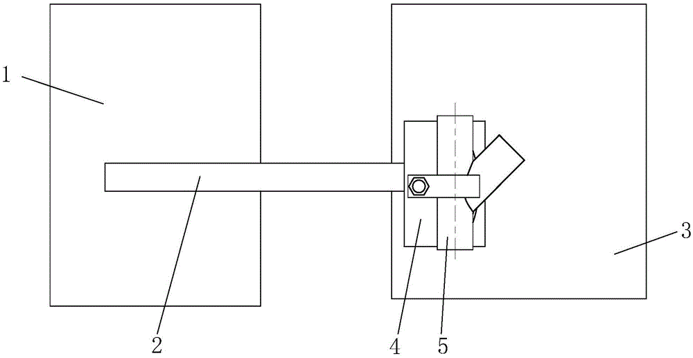
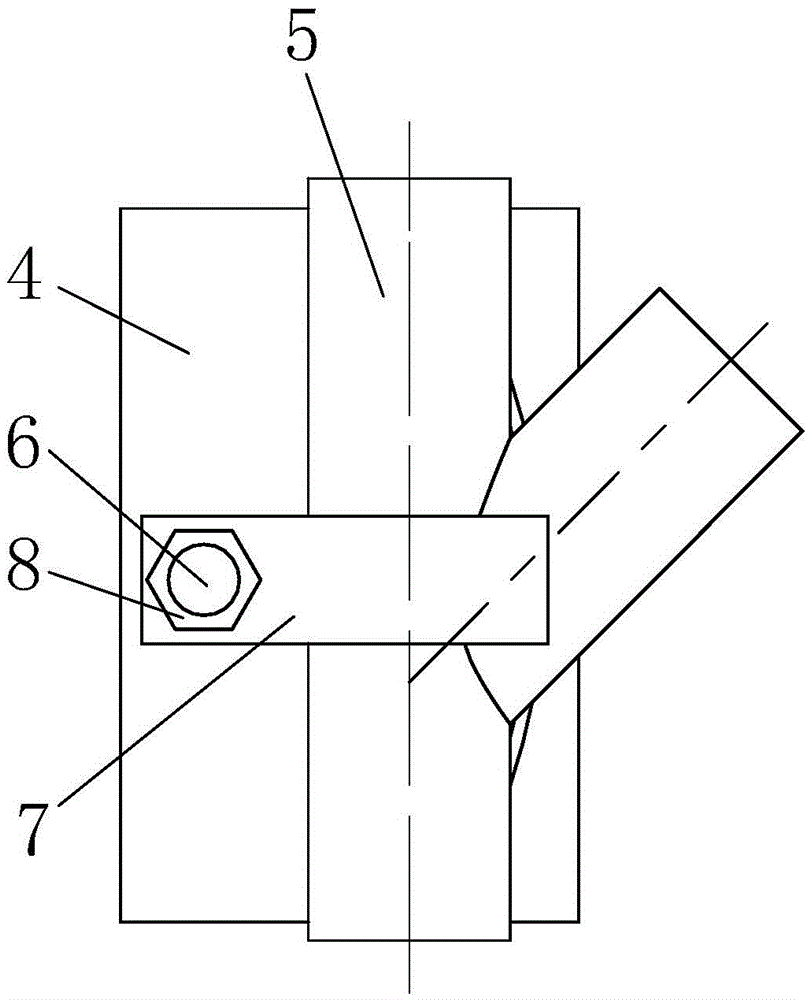
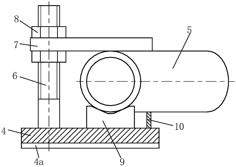
[0014] Such as Figure 1 to Figure 4 As shown, a clamping table for processing inclined three-way valves includes a first workbench 1, a guide rail beam 2, a second workbench 3, a fixture table 4, studs 6, positioning bolts 8, a pressure plate 7, and a front V-shaped Positioning block 9, rear V-shaped positioning block 11, auxiliary support rib 10, the first workbench 1 and the second workbench 3 are placed side by side, and the first workbench 1 and the second workbench 3 pass along the The guide rail beam 2 distributed in the length direction of the first workbench 1 is connected, and the lower end of the fixture table 4 is provided with a draw-in groove 4a that slides and fits with the guide rail beam 2, and the stud 6 is vertically installed on the upper left end of the fixture tabl...


PUM


Abstract

The invention relates to a clamping table for machining slanting tee joint valves. The clamping table for machining the slanting tee joint valves comprises a first worktable, a guide track beam, a second worktable, a clamp table, a stud, a positioning bolt, a pressure plate, a front V-shaped positioning block, a rear V-shaped positioning block and an auxiliary supporting rib, wherein the first worktable is connected with the second worktable through the guide track beam; a slot which is in sliding fit with the guide track beam is formed in the lower end of the clamp table; the stud is vertically mounted at the left upper end of the clamp table; the pressure plate is mounted on the stud in a sleeving manner, and is positioned on the stud by matching the positioning bolt and threads of the stud; the front V-shaped positioning block and the rear V-shaped positioning block are fixed on the clamp table from front to back; the auxiliary supporting rib is horizontally fixed at the right upper end of the clamp table; and the front end and the rear end of the auxiliary supporting rib are respectively connected with the front V-shaped positioning block and the rear V-shaped positioning block correspondingly. The clamping table for machining the slanting tee joint valves has the advantages of reasonable structural design, low production and manufacturing cost, convenience in operation and use and the like; and the slanting tee joint valves with different gradients can be clamped and positioned.

Description

technical field [0001] The invention relates to the technical field of valve production and processing, in particular to a clamping table for processing inclined three-way valves. Background technique [0002] As we all know, in the process of valve production and processing, different types of valves require special fixtures for positioning, which makes the cost of production and processing higher, especially for inclined three-way valves, because the slope of each type of inclined three-way valves is different. Not the same, the design of this jig brings difficulty. If each jig is designed with a separate jig, the production and processing costs of the product will be high, and the discarded jigs will not be recycled, resulting in serious waste of resources. Contents of the invention [0003] Aiming at the defects of the above-mentioned technologies, the present invention proposes a clamping platform for processing inclined three-way valves. [0004] A clamping table fo...

Claims


Application Information

Patent Timeline
Patent Type & Authority Applications(China)
IPC IPC(8): B23Q1/03B23Q3/06
CPCB23Q1/03B23Q3/062B23Q2703/10
Inventor 鲁明鲁传玉鲁俊
Owner WUHU JIENUO TECH
Why Eureka
Try Eureka