Unwinding and semi-automatic feeding and fabric transmitting device for wirecord fabric cutting machine

A technology of steel cord and guide device, which is applied to tires, other household appliances, household appliances, etc. It can solve the problems of inaccurate positioning, loss, material size out of tolerance and scrapping, etc., to reduce disorder and waste , The effect of ensuring accuracy

Active Publication Date: 2016-04-06
桂林中昊力创机电设备有限公司
View PDF5 Cites 2 Cited by
  • Summary
  • Abstract
  • Description
  • Claims
  • Application Information

AI Technical Summary

Problems solved by technology

[0002] At present, the main body of the steel cord cutting machine needs to meet the steel cord cutting with a width of 1000mm and a minimum angle of 15°. Because of its unique structure, the connecting part between the guide device and the cutting main machine has a large free space. There is no reference when the opening involves the front of the cutting knife of the main machine, and its position cannot be accurately positioned. The direction of the material is inconsistent with the movement direction of the clamping mechanism behind the cutting main machine whose movement direction is precisely controlled by the program, resulting in the first few knives of material cut during the initial feeding. The size is out of tolerance and scrapped, resulting in loss

Method used


Image

  • Unwinding and semi-automatic feeding and fabric transmitting device for wirecord fabric cutting machine
  • Unwinding and semi-automatic feeding and fabric transmitting device for wirecord fabric cutting machine
  • Unwinding and semi-automatic feeding and fabric transmitting device for wirecord fabric cutting machine

Examples


Embodiment Construction

[0014] The technical solutions of the present invention will be further described below in conjunction with the embodiments shown in the accompanying drawings.

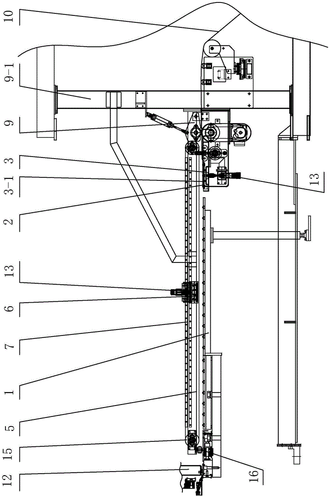
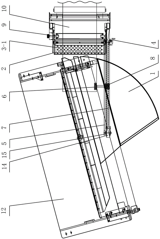
[0015] The semi-automatic feeding and delivery device of the steel cord cutting machine of the present invention includes a steel cord suction mechanism and a steel cord suction mechanism arranged between the outlet of the guiding device 9 and the arc ball table panel 1 at the entrance of the shearing machine 12, and Steel cord transmission mechanism, such as figure 1 , figure 2 shown.

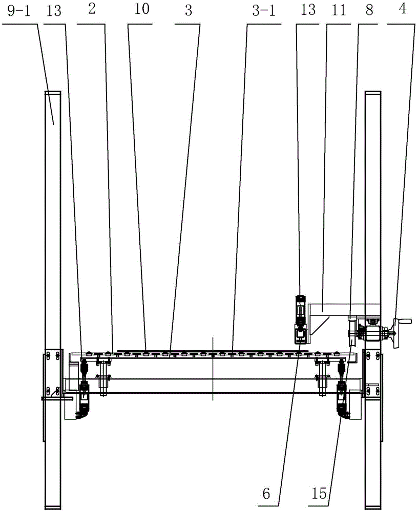
[0016] The steel cord suction mechanism is set based on the installation frame between the square tubes (9-1) on both sides of the front end of the guide device 9, and includes a distribution ball table panel 2 and a magnetic plate 3, and the cloth delivery ball table panel 2 is flat. The circular arc ball table panel 1, the magnetic plate 3 is arranged under the distribution ball table panel 2 through the lifting cylinder 13 arran...


PUM


Abstract

The invention discloses an unwinding and semi-automatic feeding and fabric transmitting device for a wirecord fabric cutting machine. The device comprises a wirecord fabric suction mechanism, a wirecord fabric sucking-up mechanism and a wirecord fabric transmitting mechanism, wherein the wirecord fabric suction mechanism and the wirecord fabric sucking-up mechanism are arranged between the outlet of an unwinding device and a circular arc ball deck plate of a shearing machine; the wirecord fabric suction mechanism comprises a fabric transmitting ball deck plate and a lifting magnetic board arranged below the fabric transmitting ball deck plate; openings corresponding to magnetic blocks on the magnetic board in position are formed in the fabric transmitting ball deck plate; the wirecord fabric transmitting mechanism comprises a linear guide rail and a sliding block; the linear guide rail is arranged in the feeding direction; the sliding block is matched with the linear guide rail in a sliding manner, and is driven by a synchronous belt driven by a handwheel to do reciprocating motion; and the wirecord fabric sucking-up mechanism comprises a magnetic sucking block which is connected with the sliding block and can ascend and descend. The side of the wireboard fabric is sucked up through the magnetic sucking block, and the handwheel is shaken to enable the magnetic sucking block to send the wirecord fabric to a position in front of a cut-off knife along the linear guide rail, so that the primary feeding precision is improved, and the material waste is reduced.

Description

technical field [0001] The invention relates to tire semi-finished product production equipment, in particular to a semi-automatic feeding and feeding device for a steel cord cutting machine. Background technique [0002] At present, the main body of the steel cord cutting machine needs to meet the steel cord cutting with a width of 1000mm and a minimum angle of 15°. Because of its unique structure, the connecting part between the guide device and the cutting main machine has a large free space. There is no reference when the opening involves the front of the cutting knife of the main machine, and its position cannot be accurately positioned. The direction of the material is inconsistent with the movement direction of the clamping mechanism behind the cutting main machine whose movement direction is precisely controlled by the program, resulting in the first few knives of material cut during the initial feeding. The size is out of tolerance and scrapped, resulting in loss. ...

Claims


Application Information

Patent Timeline
Patent Type & Authority Applications(China)
IPC IPC(8): B29D30/38B29D30/46
CPCB29D30/38B29D30/46
Inventor 彭金勇赵兴军
Owner 桂林中昊力创机电设备有限公司
Why Eureka
Try Eureka