Rolling machine and control method thereof

A technology of winding machine and winding roller, which is applied in the direction of winding strips, sending objects, and coating liquid on the surface, etc., which can solve the problems of low efficiency and large space, so as to improve processing efficiency and reduce occupation The effect of the venue

Active Publication Date: 2016-04-06
CHONGQING KEXIN PLASTIC
View PDF9 Cites 4 Cited by
  • Summary
  • Abstract
  • Description
  • Claims
  • Application Information

AI Technical Summary

Problems solved by technology

The processing, processing and winding of strip-shaped thin materials requires a large space as a whole. Since the processing, p...

Method used


Image

  • Rolling machine and control method thereof
  • Rolling machine and control method thereof
  • Rolling machine and control method thereof

Examples


Embodiment 1

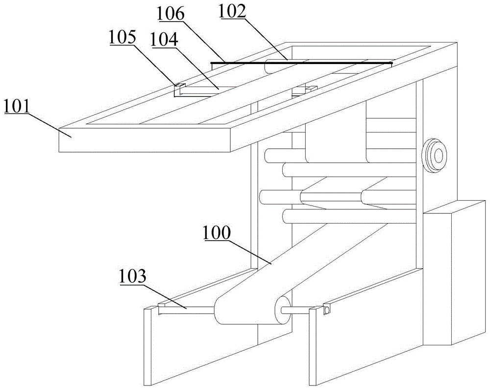
[0051] Such as figure 1 As shown, the embodiment of the present invention provides a winding machine, including a winding platform 101 , a plurality of supporting rollers 102 and a plurality of winding rollers 103 . The plurality of idler rollers 102 and the plurality of winding rollers 103 are installed on the winding platform 101 .

[0052] In order to ensure the reliability of the winding roller 103, in this embodiment, preferably, the plurality of idler rollers 102 and the plurality of winding rollers 103 are arranged parallel to each other, and the plurality of idler rollers 102 and the plurality of winding rollers The rollers 103 are staggeredly installed on the winding platform 101 from top to bottom, and the supporting rollers 102 are located above the winding rollers 103 .

[0053] Wherein, the plurality of idler rollers 102 and the plurality of winding rollers 103 are parallel to each other, which means that the plurality of idler rollers 102 and the plurality of wi...

Embodiment 2

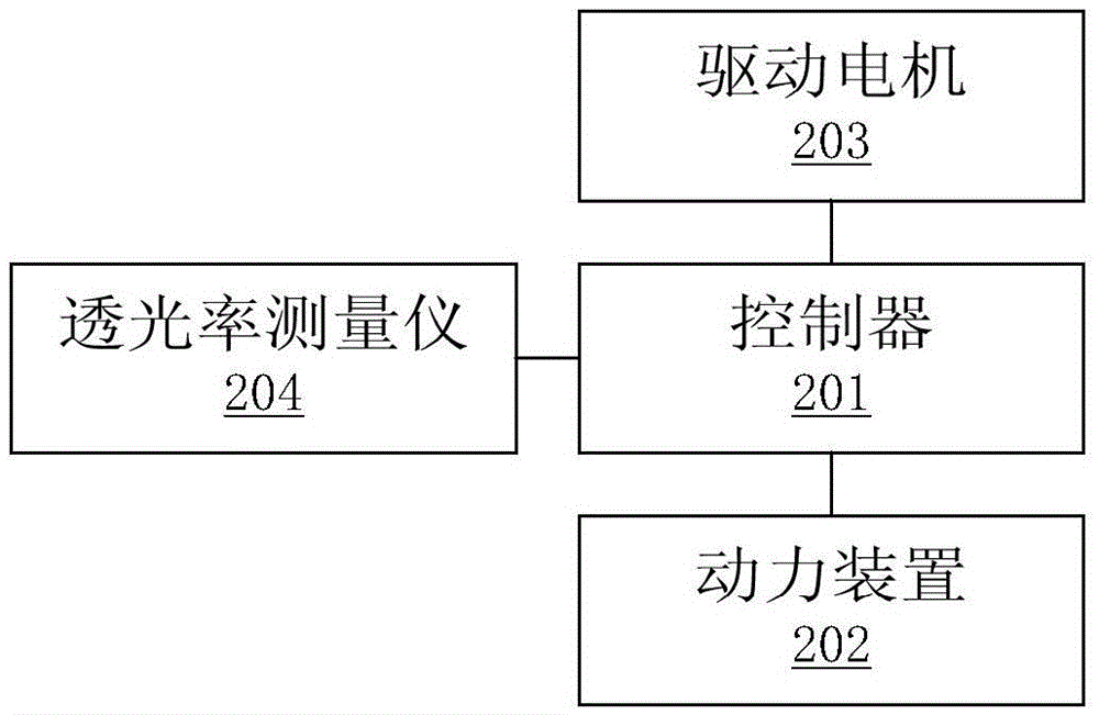
[0084] Such as Figure 9 As shown, the embodiment of the present invention provides a control method of a winder, and the winder includes a controller, a power device, a winding platform, a plurality of supporting rollers and a plurality of winding rollers. The plurality of idlers and the plurality of winding rollers are installed on the winding platform, the plurality of idlers and the plurality of winding rollers are connected with the power device, and the winding platform is also installed with The controller is connected to the dyeing device and the color fixing device, and the dyeing device and the color fixing device are located between two adjacent rollers. The dyeing device includes a rotating shaft coated with a color-absorbing material and parallel to the supporting roller, a dye storage tank is arranged under the rotating shaft, the lower part of the rotating shaft is located in the dye storage tank, and the rotating shaft A driving motor is connected, and the dri...


PUM


Abstract

The embodiment of the invention provides a rolling machine and a control method thereof. The problem that in the prior art, treatment, machining and rolling on strap-shaped thin materials belong to different treatment procedures, and consequently the efficiency of finally achieving rolling is low is solved. The rolling machine comprises a controller, a power device, a rolling platform, a plurality of carrier rollers and a plurality of wind-up rollers. The carrier rollers and the wind-up rollers are arranged on the rolling platform and connected with the power device, and dyeing devices and color fixation devices are arranged on the rolling platform and connected with the controller. The dyeing devices comprise rotary shafts coated with color absorption materials, and the rotary shafts are parallel to the carrier rollers. A dye storage tank is arranged below the rotary shafts, and the lower portions of the rotary shafts are located in the dye storage tank. The rotary shafts are connected with a drive motor, and the drive motor and the power device are connected with the controller. The controller is connected with light transmittance measurement instruments. By means of the rolling machine, rolling efficiency can be improved, and application and popularization are easy.

Description

technical field [0001] The invention relates to the technical field of mechanical processing, in particular to a winder for winding strip-shaped thin materials and a control method thereof. Background technique [0002] In the receiving part of the coil processing production line, the raw materials are usually processed and then mechanically wound into coils. In the prior art, most of the raw materials are wound into rolls by a winder. [0003] Winders are widely used in the processing production lines of paper rolls, cloth rolls, plastic coils, etc. Nowadays, most of the winders are only used for winding strip-shaped thin materials, and the processing and processing of strip-shaped thin materials need to be completed with another site and equipment. The processing, processing and winding of strip-shaped thin materials requires a large space as a whole. Since the processing, processing and winding of strip-shaped thin materials belong to different processing procedures, th...

Claims


Application Information

Patent Timeline
IPC IPC(8): B65H18/08B65H35/06B05C9/12
CPCB05C9/12B65H18/08B65H35/06B65H2301/4193B65H2404/15
Inventor 代模代平伍秋涛周文强周建兵刘彬张平
Owner CHONGQING KEXIN PLASTIC
Why Eureka
Try Eureka