Cutting fluid centralized supply-discharge and recovery system

A recovery system and cutting fluid technology, applied in the field of cutting fluid supply and drainage and processing systems, can solve the problem of inability to realize the centralized supply and discharge of cutting fluid, the effective operation of cutting fluid and the centralized recovery of waste chips, and the inability to realize the centralized supply and drainage of cutting fluid and recycling Utilize and increase the site occupancy of auxiliary equipment for processing equipment, etc., to reduce cleaning time and labor intensity, reduce maintenance frequency, and reduce processing costs

Active Publication Date: 2017-07-07
重庆雷联汽车部件有限公司
View PDF16 Cites 1 Cited by
  • Summary
  • Abstract
  • Description
  • Claims
  • Application Information

AI Technical Summary

Problems solved by technology

[0002] In the prior art, for the treatment of cutting fluid produced by large-scale machines, manual cleaning is generally used for processing or additional equipment is used to collect and recycle the cutting fluid of each machine tool separately. If manual cleaning is used, not only The labor intensity of the workers is high, and the cutting fluid may be scattered everywhere during the cleaning process, making the operating environment of the equipment worse, which will cause the servo motor of the machine tool to circulate the cutting fluid to fail, increase the frequency and cost of equipment maintenance, and cannot realize the goal of the processing industry. For clean production, if additional equipment is used to collect and recycle the cutting fluid of each machine tool separately, the cost will be high, and at the same time it will increase the space occupied by the auxiliary equipment of the processing equipment, and it will not be possible to realize the centralized supply, drainage and reuse of cutting fluid, which will affect production efficiency;
[0003] In the existing similar schemes, it is impossible to realize the effective operation of centralized supply and discharge of cutting fluid and centralized recovery of cutting fluid and waste chips on large-scale machines

Method used


Image

  • Cutting fluid centralized supply-discharge and recovery system
  • Cutting fluid centralized supply-discharge and recovery system
  • Cutting fluid centralized supply-discharge and recovery system

Examples


Embodiment Construction

[0020] Below in conjunction with accompanying drawing and embodiment the present invention will be further described:

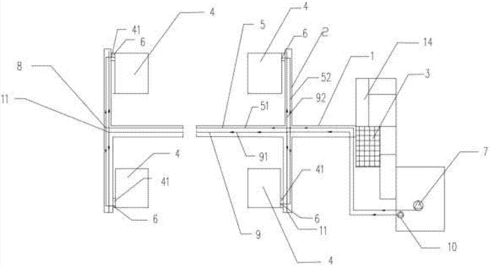
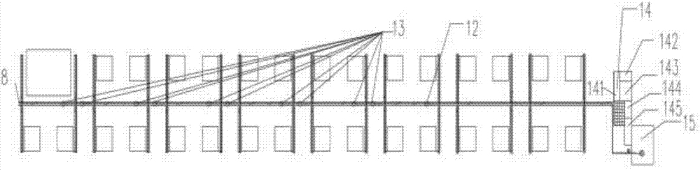
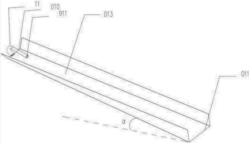
[0021] like Figures 1 to 4 As shown, a cutting fluid centralized supply and drainage and recovery system includes a main water tank 1 and several branch water tanks 2 connected to each other; the main water tank 1 communicates with the recovery pool 3; the recovery pool is lower than the main water tank; the starting end of the branch water tank 2 can be It communicates with the cutting fluid outlet 41 of the machine tool 4 .

[0022] The recovery tank is connected to the water supply pipeline 5, and the end of the water supply pipeline can be connected with the cutting fluid supply port 6 of the machine tool. The water supply pipeline includes a main water supply pipeline 51 and a branch water supply pipeline 52 that communicate with each other. Extending along the branch water tank 2; the first water pump 7 is arranged on the pipeline of the main water su...


PUM


Abstract

The invention discloses a cutting fluid centralized supply-discharge and recovery system. The system is characterized in that: it comprises a main water tank and several branch water tanks that are communicated with each other; the main water tank is communicated with a recovery pool; the recovery pool is lower than the main water tank; and starting ends of the branch water tanks can be communicated with cutting fluid outlets of machine tools. The system provided by the invention has the advantages of simple structure and obvious economic benefits, can achieve no chip and water on a workshop site, takes the lead to realize clean production of the machining industry, is conducive to processing equipment maintenance, reduces maintenance frequency, and lowers the maintenance cost, reduces the occupation of processing accessory equipment, and is convenient for operation. The system provided by the invention enables recycling of cutting fluid, a cutting fluid mother pool is underground and does not spoil or deterioriate easily; the cutting fluid has better cooling effect, and is more conducive to machining; also the waste chips generated by machining are subjected to centralized recovery, the cutting fluid recycling, cutting fluid filtration treatment, cutting fluid cyclic utilization, cutting fluid storage and other functions are uniformly realized in one system, energy sources are saved, and the cost is lowered.

Description

technical field [0001] The invention relates to a cutting fluid supply and discharge and treatment system used in machining processes, in particular to a cutting fluid centralized supply and discharge and waste chip recovery system for large-scale numerically controlled machine tools. Background technique [0002] In the prior art, for the treatment of cutting fluid produced by large-scale machines, manual cleaning is generally used for processing or additional equipment is used to collect and recycle the cutting fluid of each machine tool separately. If manual cleaning is used, not only The labor intensity of the workers is high, and the cutting fluid may be scattered everywhere during the cleaning process, making the operating environment of the equipment worse, which will cause the servo motor of the machine tool to circulate the cutting fluid to fail, increase the frequency and cost of equipment maintenance, and cannot realize the goal of the processing industry. For cle...

Claims


Application Information

Patent Timeline
Patent Type & Authority Applications(China)
IPC IPC(8): B01D36/02B23Q11/00C02F1/00C02F103/34
CPCB01D36/02C02F1/001B23Q11/00C02F2301/08C02F2103/34C02F2001/007Y02P70/10
Inventor 苟建华
Owner 重庆雷联汽车部件有限公司
Why Eureka
Try Eureka