Gas sensor chip and gas sensor provided therewith

a gas sensor and chip technology, applied in the field of small, can solve the problems of increasing costs, reducing the service life of the sensor, and limiting the location of installation, so as to reduce the frequency of maintenance of the gas sensor, increase the durability of the gas sensor chip itself, and improve the accuracy of the quantity detection

Inactive Publication Date: 2009-08-06
YAMATAKE HONEYWELL CO LTD
View PDF0 Cites 14 Cited by
  • Summary
  • Abstract
  • Description
  • Claims
  • Application Information

AI Technical Summary

Benefits of technology

[0025]The gas sensor above enables a comparison of the outputs of the temperature measuring resistors of the gas sensor chip that is provided with the oxidation combustion catalyst and the gas sensor chip that is not provided with the oxidation combustion catalyst, to thereby enable the detection of only the change in temperature that is due to the combustion of the non-combusted gas that is included in the exhaust gas, without being affected by changes in temperature of the exhaust gas itself or changes in the ambient temperature. This enables a more accurate detection of the quantity of the non-combusted gas constituent in the exhaust gas.
[0026]Additionally, the durability of the gas sensor chip itself is increased by the measurement resistor not coming into direct contact with the gas, enabling a reduction in the frequency of maintenance of the gas sensor.
[0027]The present invention enables the provision of a gas sensor chip, and of a gas sensor provided therewith, capable of providing stable output characteristics over an extended period of time, even when equipped in a harsh environment such as a boiler smokestack carrying exhaust gasses.

Problems solved by technology

In the contact combustion-type gas sensor such as set forth in JP '909 there are shortcomings such as the overall size being large, the sensor itself tending to increase costs, and there being constraints on the location of installation.
In a gas sensor such as set forth above, there are cases wherein gasses that are a hazardous environment to the sensor structural materials have been selected as being subject to measurement, and there has also been, for example, dust and the like, causing service life of the sensor to be reduced by this type of measurement environment.
The shorter the service life of the sensor, the more frequent the maintenance (or the more frequently the sensor is replaced), producing a problem in terms of ensuring operation and in terms of operating costs.

Method used


Image

  • Gas sensor chip and gas sensor provided therewith
  • Gas sensor chip and gas sensor provided therewith
  • Gas sensor chip and gas sensor provided therewith

Examples


Embodiment Construction

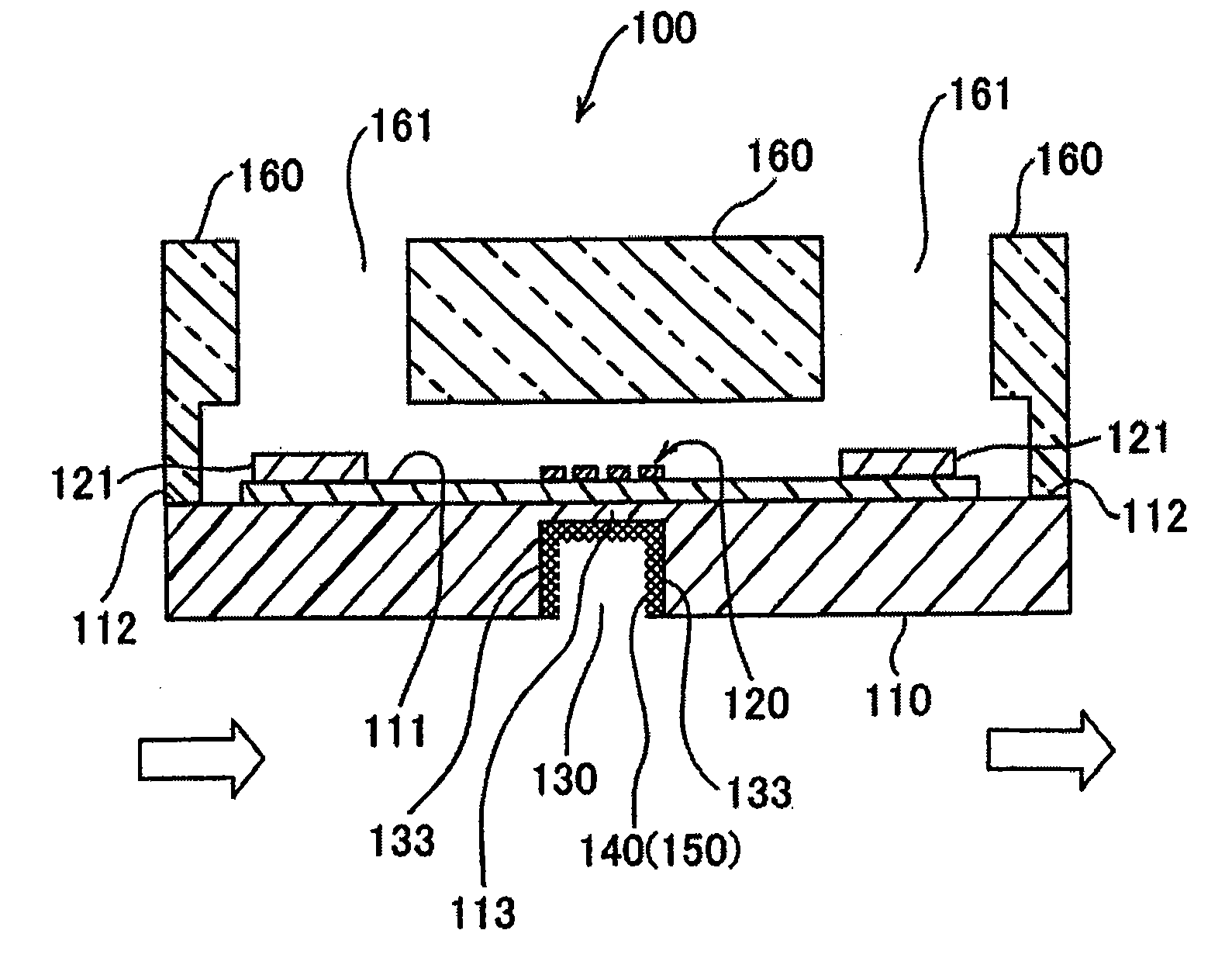
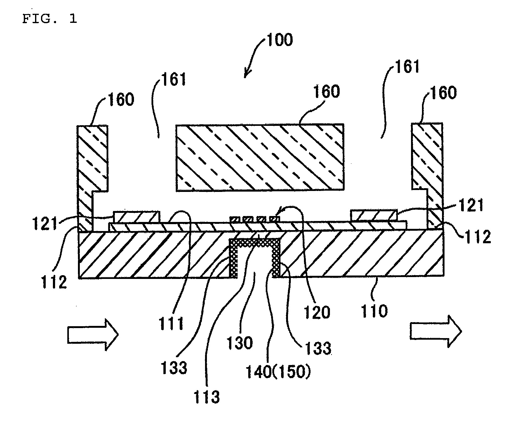
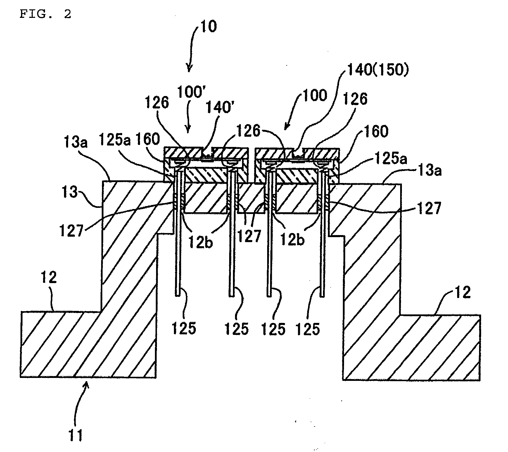
[0034]A gas sensor chip 100, and a gas sensor 10 provided therewith, which are one example of embodiment according to the present invention, will be explained in detail below referencing the figures. The gas sensor chip 100 that is one embodiment of the present invention will be explained first. FIG. 1 is a cross-sectional diagram illustrating the gas sensor chip 100 according to one example of embodiment according to the present invention, along the direction that is perpendicular to the surface of the base substrate 110 wherein a temperature measuring resister is fabricated.

[0035]This gas sensor chip 100, as illustrated in FIG. 1, comprises a base substrate 110, a temperature measuring resister 120 that is patterned in the surface on one side of the base substrate 110, a recessed portion 130 that is formed on the opposite side of the base substrate 110 facing the temperature measuring resister 120, a porous silicon layer 140 provided on the inside surface of the recessed portion 1...


PUM

PropertyMeasurementUnit
temperatureaaaaaaaaaa
temperaturesaaaaaaaaaa

Abstract

To provide a gas sensor chip, and a gas sensor provided therewith, capable of producing stable output characteristics over an extended period of time even when installed in a harsh environment such as a boiler smokestack carrying exhaust gasses. There is a backside structure wherein a catalyst carrier that contacts a gas to be measured is disposed on one side of a thermal conductor, a temperature sensing portion is disposed in a location that does not contact the gas to be measured, on the other side of the thermal conductor, and the temperature sensing portion measures the temperature corresponding to the temperature of the catalyst carrier through the thermal conductor, to enable the sensing of the amount of flow over an extended period of time without the temperature sensing portion being negatively affected by the gas to be measured.

Description

CROSS-REFERENCE TO RELATED APPLICATION[0001]The present application claims priority under 35 U.S.C. §119 to Japanese Patent Application No. 2008-025783 filed on Feb. 5, 2008. The content of the application is incorporated herein by reference in its entirety.FIELD OF TECHNOLOGY[0002]The present invention relates to a small gas sensor chip of a contact combustion type, having a superior durability, and to a gas sensor provided therewith.BACKGROUND OF THE INVENTION[0003]Contact combustion-type gas sensors for detecting quantities of constituent carbon monoxide, which is a non-combusted gas in, for example, and exhaust gas, having high sensitivity to only non-combusted gasses such as carbon monoxide, have been known conventionally. (See, for example, Japanese Unexamined Patent Application Publication H8-226909 (“JP '909”) (Pages 3-4 and FIG. 1)).[0004]In the contact combustion type gas sensor set forth in JP '909, the gas detecting element and supplementary elements that structure a bri...

Claims


Application Information

Patent Timeline
Patent Type & Authority Applications(United States)
IPC IPC(8): G01N7/06G01N25/18
CPCG01N27/18G01N25/18
Inventor TOKUDA, TOMOHISAMATSUNAGA, SHINSUKENAKAZAKI, YOSHIYUKIHOTTA, KOUICHIROU
Owner YAMATAKE HONEYWELL CO LTD
Why Eureka
Try Eureka