Insulation structure and insulation method
- Summary
- Abstract
- Description
- Claims
- Application Information
AI Technical Summary
Benefits of technology
Problems solved by technology
Method used
Image
Examples
embodiment 1
[0095]2. The insulation structure , wherein
[0096]the machinable ceramic or the porous ceramic has Vickers hardness of 5 GPa or less.
[0097]3. The insulation structure according to Embodiment 1 or 2, wherein
[0098]the machinable ceramic includes boron nitride.
[0099]4. The insulation structure according to any one of Embodiments 1 to 3, wherein
[0100]the porous ceramic includes porous alumina.
[0101]5. The insulation structure according to any one of Embodiments 1 to 4, wherein
[0102]at least one of the first protection member and the second protection member is made of a conductive carbon material.
[0103]6. The insulation structure according to any one of Embodiments 1 to 5, wherein
[0104]at least one of the first protection member and the second protection member comprises an adsorption surface adsorbing the contamination particles.
embodiment 6
[0105]7. The insulation structure , wherein
[0106]the adsorption surface has a roughness factor of 200 or higher.
[0107]8. The insulation structure according to any one of Embodiments 1 to 7, wherein
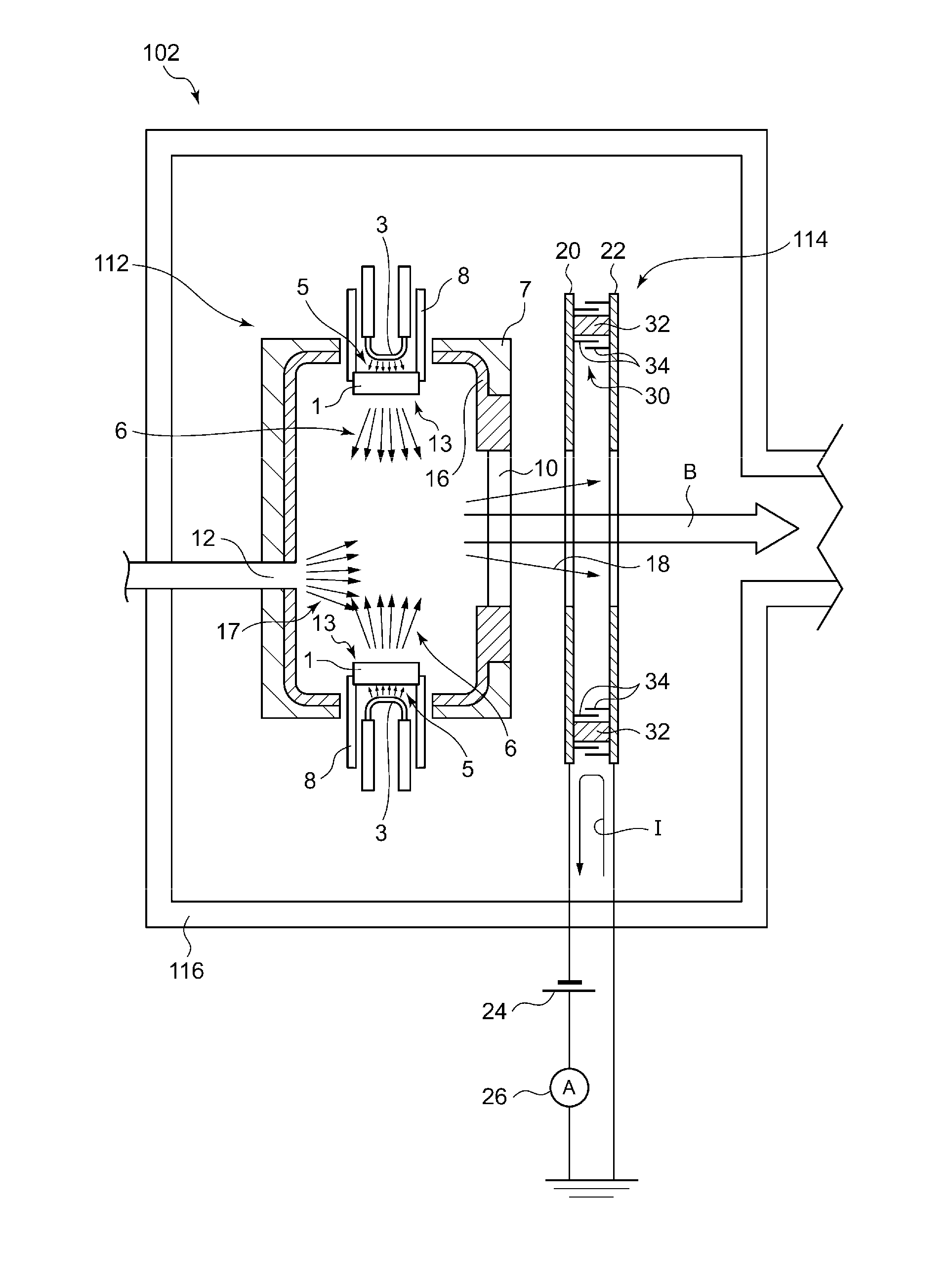
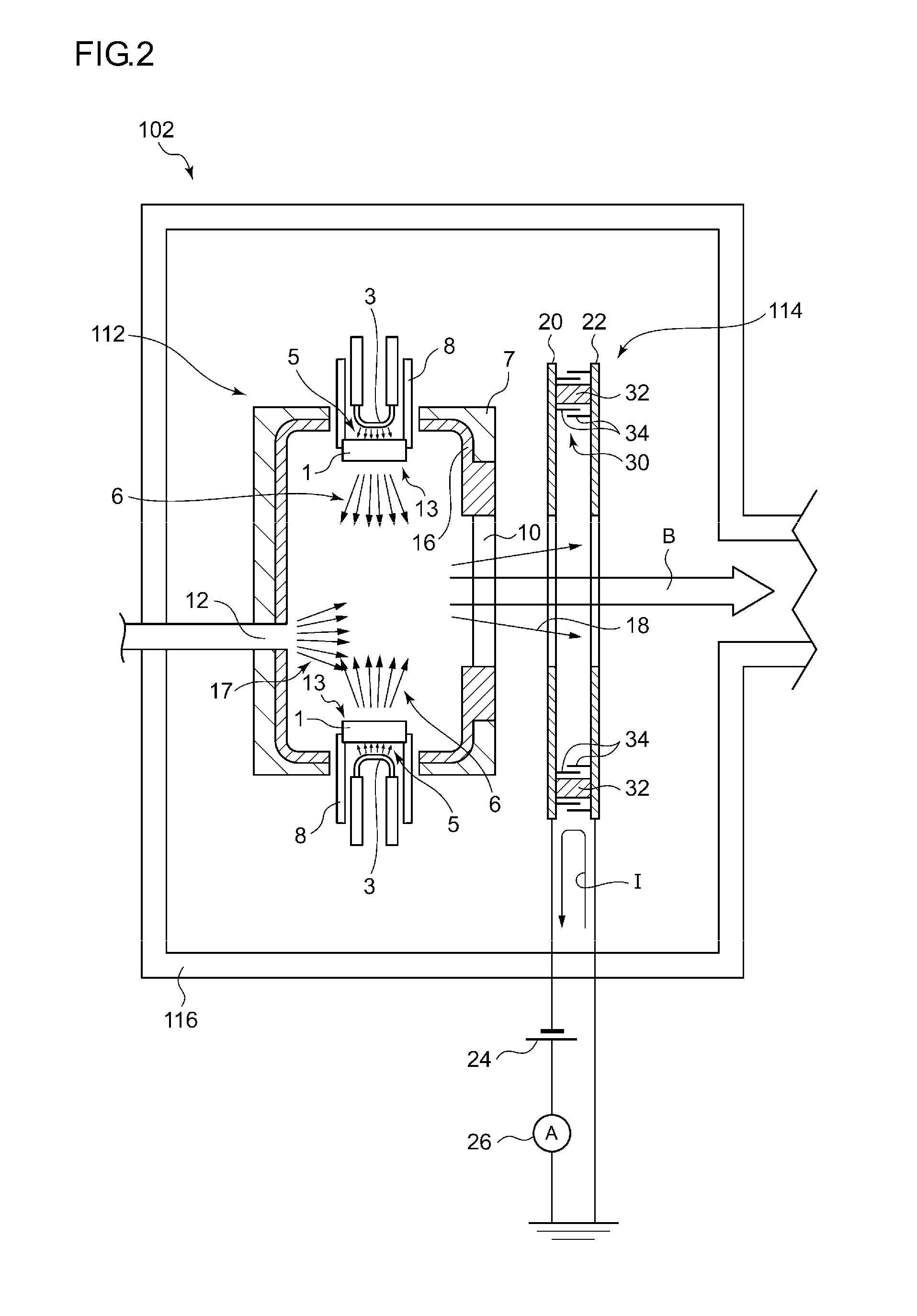
[0108]the insulation member comprises a middle part between the first part and the second part, and the middle part has a recess on a surface thereof, and wherein
[0109]the first protection member and the second protection member are arranged to form a gap allowing entry of the contamination particles between the first protection member and the second protection member, and the recess is in vicinity of the gap.
[0110]9. The insulation structure according to any one of Embodiments 1 to 8, wherein
[0111]the first protection member extends between the second protection member and the insulation member to block a line of sight from an end of the second protection member proximate to the first electrode to an end of the insulation member on a side of the first electrode.
[0112]10. The insulation st...
embodiment 11
[0119]12. The insulation structure , wherein
[0120]the first electrode has a first positioning recess in which the first contact portion is fitted, and / or
[0121]the second electrode has a second positioning recess in which the second contact portion is fitted.
[0122]13. The insulation structure according to Embodiment 11 or 12, wherein
[0123]the first part is attached to the first electrode by a first fastening member penetrating the first electrode and the first contact portion, and / or
[0124]the second part is attached to the second electrode by a second fastening member penetrating the second electrode and the second contact portion.
[0125]14. The insulation structure according to any one of Embodiments 1 to 13, wherein
[0126]the plasma generating section comprises an inner wall that contains carbon.
[0127]15. The insulation structure according to Embodiment 1, comprising:
[0128]a single protection member on a side of the first electrode instead of the first protection member and the secon...
PUM
 Abstract
Description
Claims
Application Information
 - R&D
- Intellectual Property
- Life Sciences
- Materials
- Tech Scout
- Unparalleled Data Quality
- Higher Quality Content
- 60% Fewer Hallucinations
Browse by: Latest US Patents, China's latest patents, Technical Efficacy Thesaurus, Application Domain, Technology Topic, Popular Technical Reports.
© 2025 PatSnap. All rights reserved.Legal|Privacy policy|Modern Slavery Act Transparency Statement|Sitemap|About US| Contact US: help@patsnap.com


