System for reducing maintenance frequency for bolts and nuts of wind turbine

Inactive Publication Date: 2017-01-26
LI KEVIN SHENG YONG
View PDF7 Cites 8 Cited by
  • Summary
  • Abstract
  • Description
  • Claims
  • Application Information

AI Technical Summary

Benefits of technology

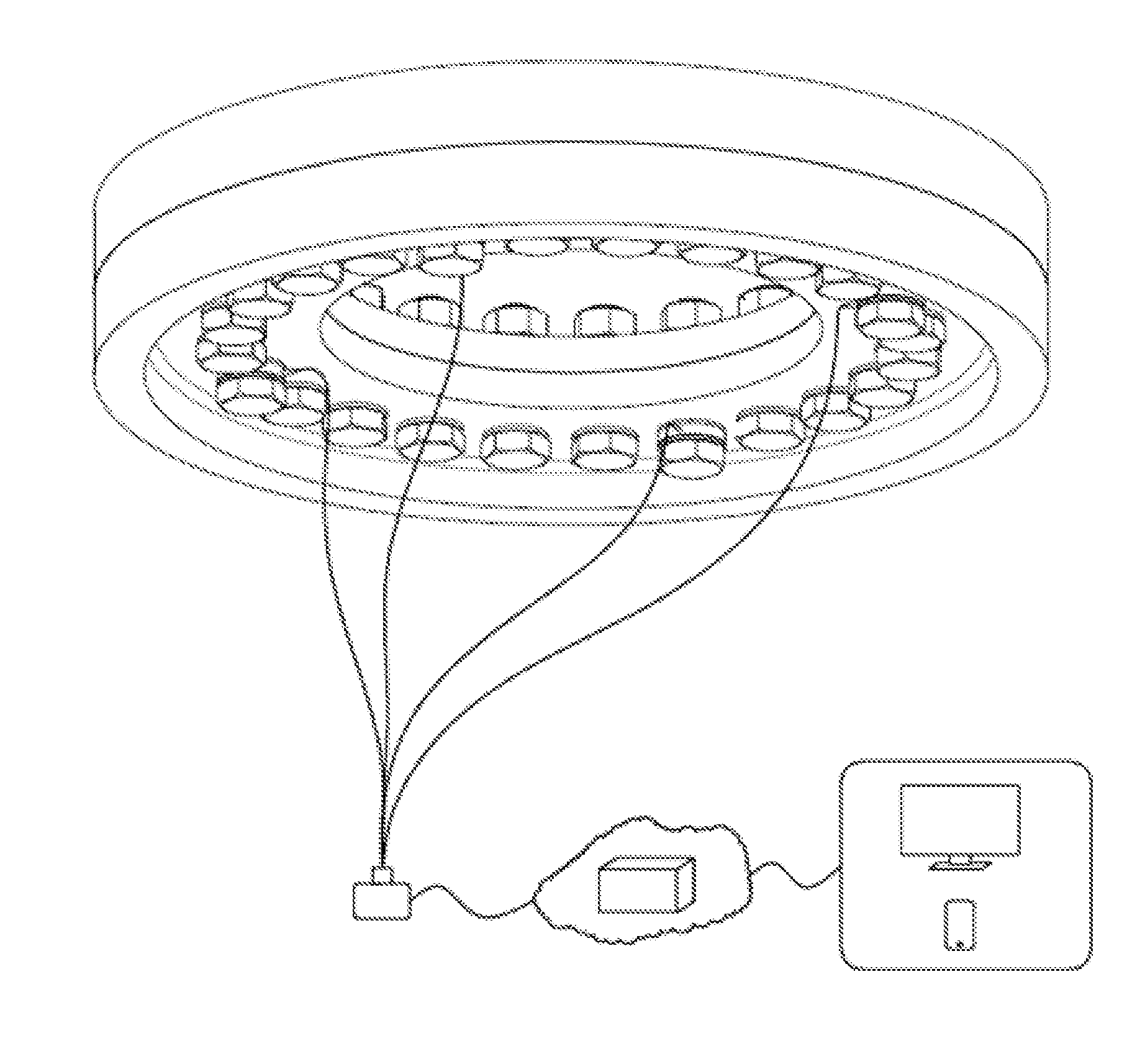
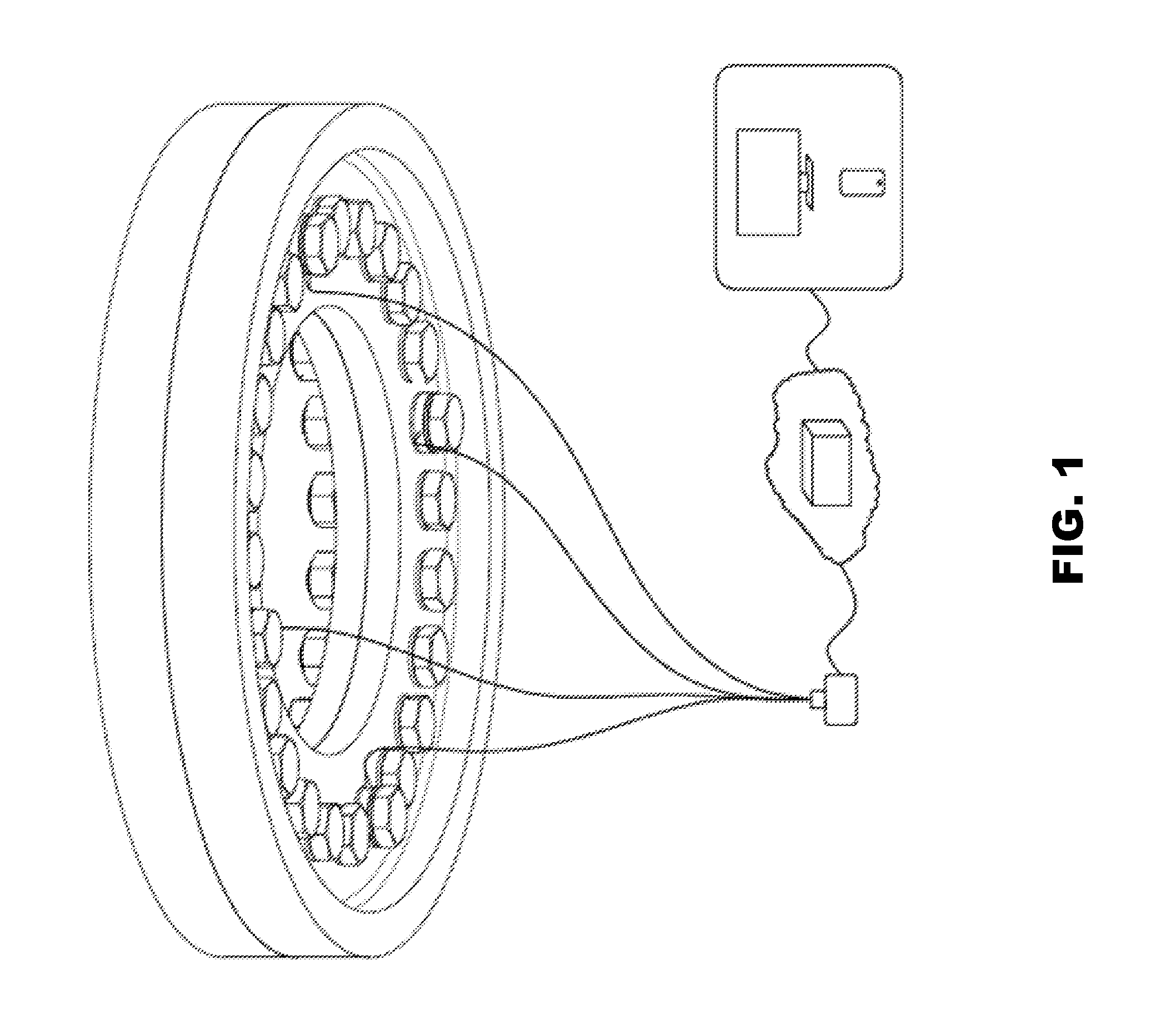
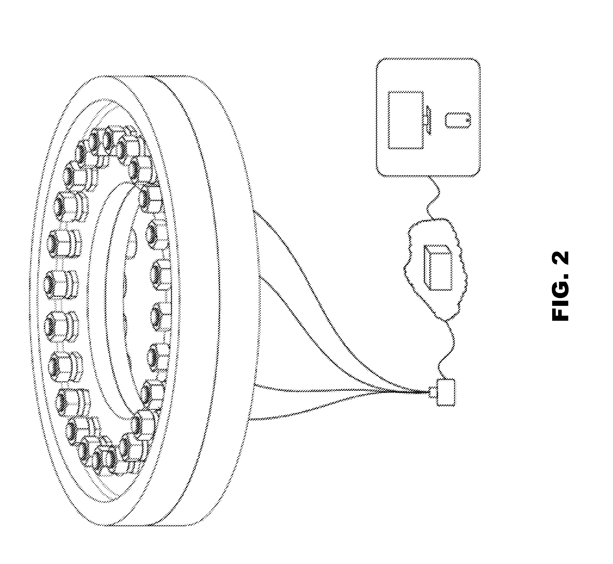
[0004]The present invention provides a system for reducing maintenance frequency of a wind turbine which comprises a plurality of fastening units, a PC data collector, a server and a terminal. The fastening unit has a bolt, an upper spacer and a lower spacer, a sensor, a wind turbine parts including flanges, bearing rings or other connecting parts, a threaded ring, a washer and a nut. The bolt has a bolt head and a threaded segment which are respectively formed at a lower end and an upper portion thereof. The sensor is disposed on the bolt together with the two spacers which are coupled on both sides of the sensor, and the bolt with the spacers and sensor penetrates though the wind turbine parts, the threaded ring and the washer sequentially, and engages with the nut to secure the components on the bolt. The upper spacer coupled between the sensor and a lower surface of the wind turbine parts is configured to prevent relative rotation occurred there between, and an upper surface of the washer is a processing plane and is coupled with a lower surface of the nut. Moreover, an inner periphery of the washer comprises an inner spline teeth which is configured to engage with an outer spline formed at an outer periphery of the threaded ring such that the threaded ring is configured to only upwardly or downwardly move along the inner spline teeth of the washer without relative rotation, and the washer is engaged with the wind turbine parts to prevent relative rotation occurred there between. Furthermore, the threaded ring is engaged with the threaded segment of

Problems solved by technology

Also, the parts connected by traditional nuts cannot sustain for a long time and needs to be inspected and replaced frequently, which increases the risk of accidents and wastes the time and labors.
Moreover, although the nuts betw

Method used


Image

  • System for reducing maintenance frequency for bolts and nuts of wind turbine
  • System for reducing maintenance frequency for bolts and nuts of wind turbine
  • System for reducing maintenance frequency for bolts and nuts of wind turbine

Examples


Example

[0013]The detailed description set forth below is intended as a description of the presently exemplary device provided in accordance with aspects of the present invention and is not intended to represent the only forms in which the present invention may be prepared or utilized. It is to be understood, rather, that the same or equivalent functions and components may be accomplished by different embodiments that are also intended to be encompassed within the spirit and scope of the invention.

[0014]Unless defined otherwise, all technical and scientific terms used herein have the same meaning as commonly understood to one of ordinary skill in the art to which this invention belongs. Although any methods, devices and materials similar or equivalent to those described can be used in the practice or testing of the invention, the exemplary methods, devices and materials are now described.

[0015]All publications mentioned are incorporated by reference for the purpose of describing and disclos...


PUM


Abstract

A system for reducing maintenance frequency for bolts and nuts of a wind turbine comprises a plurality of fastening units, a PC data collector, a server and a terminal. The fastening unit has a bolt sequentially penetrates through a lower spacer, a sensor, an upper spacer, a wind turbine parts, a threaded ring, and a washer, and then a nut is engaged and tightly fastened on the bolt. With the fastening units, the system applied to the wind turbine is configured to create a double nut locking system thereby maintaining a preload tension force of the bolt in a safety operation range. Also, through the monitoring system including the sensor connected to the terminal through the PLC data collector and the server, a user can receive the real-time monitoring data of the preload tension force of the bolt to maintain and repair the wind turbine efficiently thereby preventing accidents.

Description

FIELD OF THE INVENTION[0001]The present invention relates to a system for bolts and nuts of a wind turbine and more particularly to a system capable of reducing maintenance frequency for bolts and nuts of a wind turbine.BACKGROUND OF THE INVENTION[0002]Generally, a wind turbine comprises a segmental tower, an engine room and a plurality of blades, and the components are usually connected and engaged with each other through a plurality bolts and nuts which is a manner convenient to engage or disengage parts of a large-scale mechanical equipment or apparatus. Currently, a kind of traditional nut which is tightened by fastening approach is applied to the connection between the components such as flanges, bearing rings and bearing seats of the wind turbine. However, since the surfaces between each two parts of the wind turbine, even at the same part but different positions, have different frictions, each of fastening degree of nuts needs to be precise to prevent loosening connection bet...

Claims


Application Information

Patent Timeline
IPC IPC(8): F03D17/00G01N3/08
CPCG01N3/08F03D17/00F05B2260/301
Inventor LI, KEVIN SHENG-YONG
Owner LI KEVIN SHENG YONG
Why Eureka
Try Eureka