Thin-film solar cell manufacturing apparatus

Inactive Publication Date: 2011-05-05
ULVAC INC
View PDF2 Cites 2 Cited by
  • Summary
  • Abstract
  • Description
  • Claims
  • Application Information

AI Technical Summary

Benefits of technology

[0031]According to the aspect of the present invention, in the film forming chamber, only the transfer rail is provided without a drive source for transferring the carrier. Accordingly, it is not necessary to perform maintenance on a drive source within the film forming chamber unlike in the conventional technique, and the maintenance frequency of the film forming chamber can be reduced to improve production efficiency.

Problems solved by technology

However, due to material shortages of Si or the like, demand has recently been increasing for thin-film solar cells formed with a thin-film Si-layer in which manufacturing costs are low and the risk of material shortages is low.
Additionally, since the μc-Si layer needs to uniformly form a good microcrystalline layer, there is a limit on increasing a film formation rate.

Method used


Image

  • Thin-film solar cell manufacturing apparatus
  • Thin-film solar cell manufacturing apparatus
  • Thin-film solar cell manufacturing apparatus

Examples


Embodiment Construction

[0068]A thin-film solar cell manufacturing apparatus related to an embodiment of the present invention will be described below with reference to FIGS. 1 to 28.

Thin-film Solar Cell

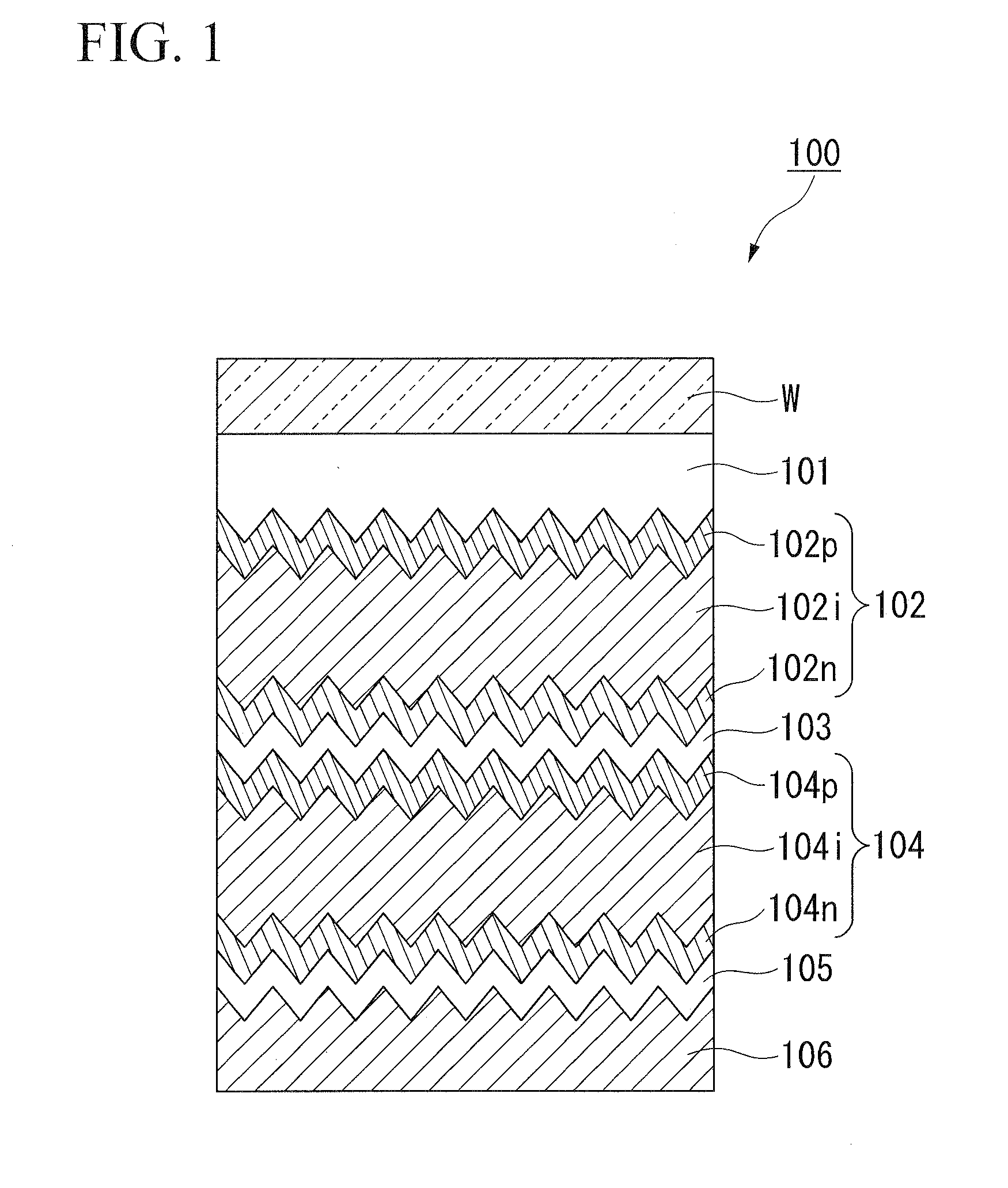
[0069]FIG. 1 is a schematic sectional view of a thin-film solar cell. As shown in FIG. 1, in a thin-film solar cell 100, a substrate W which constitutes the surface of the thin-film solar cell 100, a top electrode 101 made of a transparent-electroconductive film, a top cell 102 made of amorphous silicon, an intermediate electrode 103 made of a transparent-electroconductive film, a bottom cell 104 made of microcrystalline silicon, a buffer layer 105 made of a transparent-electroconductive film, and a back electrode 106 made of a metal film are laminated in the top-bottom order (from the top to the bottom) of the drawing. Among these, the top electrode 101 is laminated on the substrate W. The intermediate electrode 103 is laminated between the top cell 102 and the bottom cell 104. That is, the thin-film solar...


PUM


Abstract

A thin-film solar cell manufacturing apparatus includes a film forming chamber that is evacuated to a reduced pressure and forms a film on a substrate using a CVD method; a loading-ejecting chamber that is connected to the film forming chamber via a first opening-closing part and that is switchable between atmospheric pressure and reduced pressure; transfer rail that is laid at the film forming chamber and the loading-ejecting chamber; a carrier that holds the substrate and moves along the transfer rail; and a carrier transfer mechanism that transfers the carrier, wherein, the carrier transfer mechanism is provided in the loading-ejecting chamber to transfer the carrier between the film forming chamber and the loading-ejecting chamber.

Description

TECHNICAL FIELD[0001]The present invention relates to a thin-film solar cell manufacturing apparatus.[0002]Priority is claimed on Japanese Patent Application No. 2008-149939 filed on Jun. 6, 2008, the contents of which are incorporated herein by reference.BACKGROUND ART[0003]Most current solar cells are a single crystal Si type solar cell and a polycrystal Si type solar cell. However, due to material shortages of Si or the like, demand has recently been increasing for thin-film solar cells formed with a thin-film Si-layer in which manufacturing costs are low and the risk of material shortages is low. Moreover, in addition to conventional thin-film solar cell with only an a-Si (amorphous silicon) layer, a demand for tandem-type thin-film solar cells has recently been increasing, in which the conversion efficiency of the tandem-type thin-film solar cells is improved by laminating an a-Si-layer and a μc-Si (microcrystalline silicon) layer.[0004]A plasma-CVD apparatus is often used for ...

Claims


Application Information

Patent Timeline
IPC IPC(8): C23C16/503C23C16/458
CPCC23C16/4587H01L21/67161H01L21/67167H01L21/67173Y02E10/545H01L21/67781H01L31/077H01L31/1824H01L21/67754Y02E10/547Y02P70/50
Inventor SHIMIZU, YASUOOGATA, HIDEYUKIMATSUMOTO, KOICHINOGUCHI, TAKAFUMIWAKAMORI, JOUJIOKAYAMA, SATOHIROMORIOKA, YAWARASUGIYAMA, NORIYASUSHIGETA, TAKASHIKURIHARA, HIROYUKI
Owner ULVAC INC
Why Eureka
Try Eureka