Membrane distillation module and wastewater treatment apparatus

Inactive Publication Date: 2016-02-11
SUMITOMO ELECTRIC IND LTD
View PDF2 Cites 10 Cited by
  • Summary
  • Abstract
  • Description
  • Claims
  • Application Information

AI Technical Summary

Benefits of technology

[0039]As described above, adopting the membrane distillation module of the present invention using the porous membrane with the oil-repellent layer having the oil-repellent function provided on the surface of the heat-resistant hydrophobic porous membrane, an oil component contained in wastewater can be reduced/prevented from adhering to the surface of the porous membrane. Thus, maintenance frequency for the porous membrane can be reduced to reduce running cost, and productivity can be improved. In particular, since wat

Problems solved by technology

Since many steps are required in this way, initial cost and maintenance cost increase.
There are many problems, such as change in performance due to interfering

Method used


Image

  • Membrane distillation module and wastewater treatment apparatus
  • Membrane distillation module and wastewater treatment apparatus
  • Membrane distillation module and wastewater treatment apparatus

Examples


Example

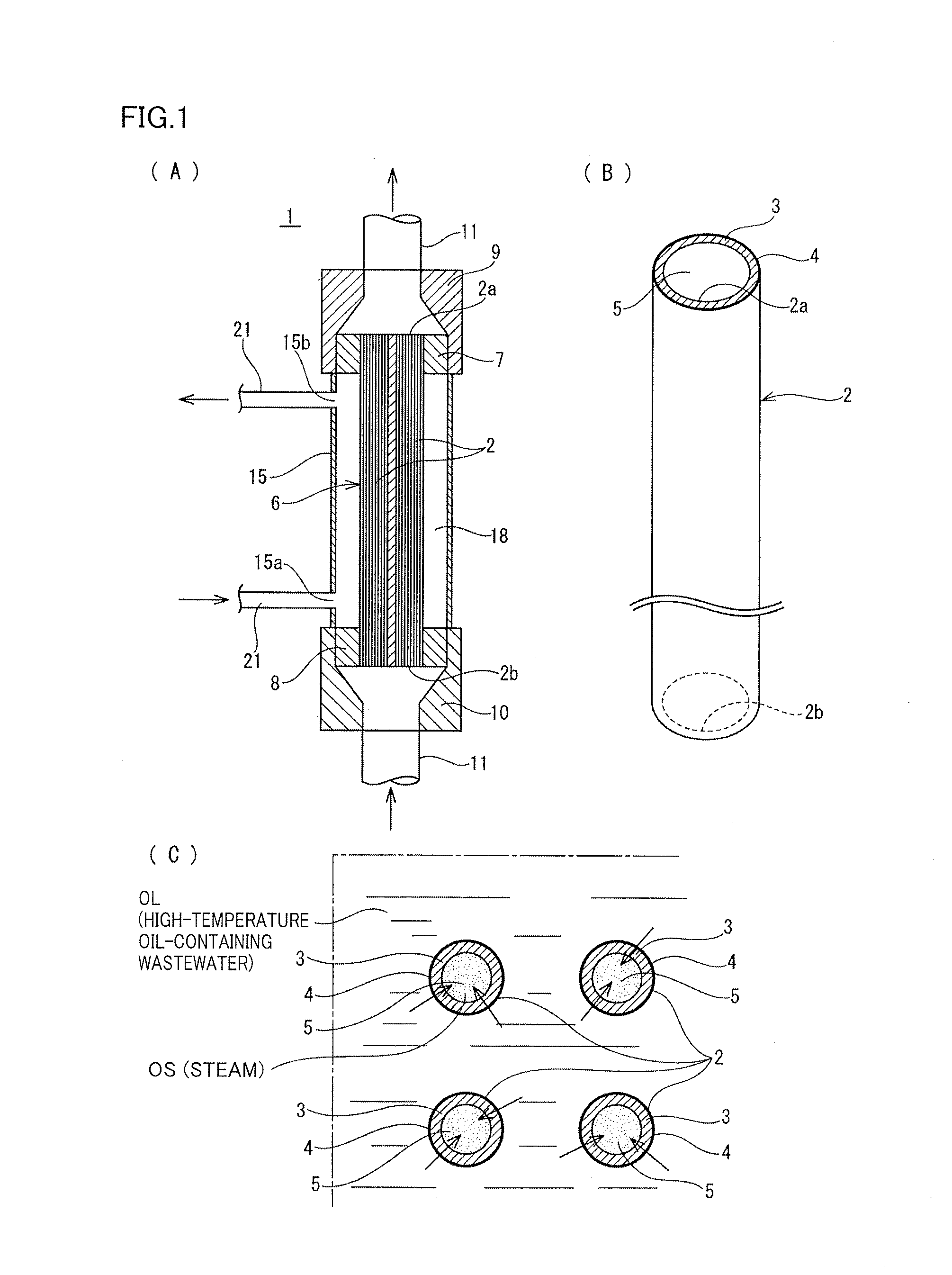
[0046]FIG. 1 shows a membrane distillation module of a first embodiment of the present invention.

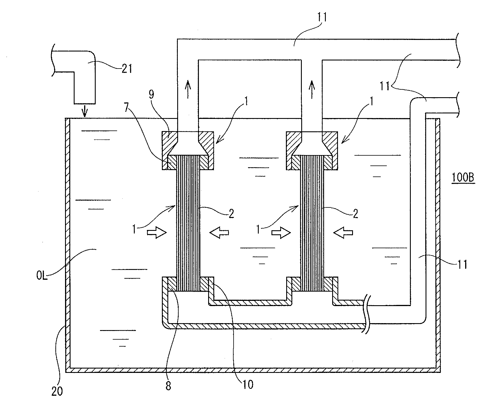
[0047]A membrane distillation module 1 of the embodiment purifies high-temperature oil-containing wastewater through membrane distillation.

[0048]Membrane distillation module 1 adopts a hollow fiber membrane 2 shown in FIG. 1 at (B) as a porous membrane for membrane distillation.

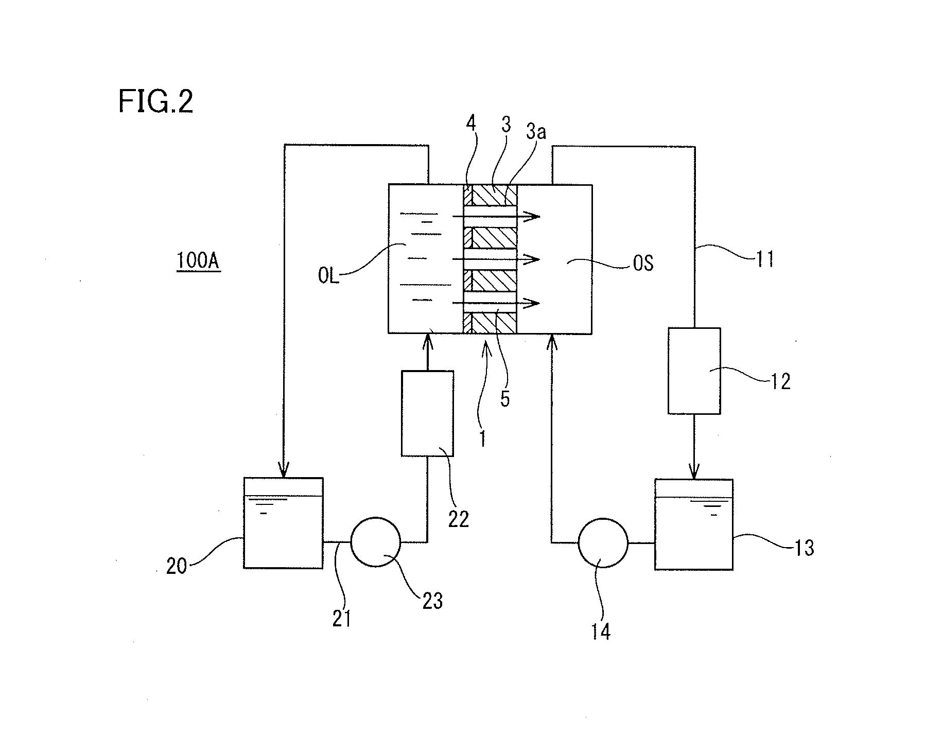
[0049]In hollow fiber membrane 2, a base membrane 3 is implemented by an expanded PTFE porous membrane, and an oil-repellent layer 4 held by impregnating the expanded PTFE porous membrane with a solution containing polymer having a fluorinated alkyl side chain having the oil-repellent function in such a mode that holes 3a (shown in FIG. 2) of base membrane 3 are not closed is provided on the outer peripheral surface of porous membrane 3.

[0050]The oil-repellent polymer used for oil-repellent layer 4 only needs to be a substance having the oil-repellent function, and is not limited to the polymer having the fluorina...

Example

[0067]A membrane distillation module of a second embodiment is shown in FIG. 4.

[0068]In a hydrophobic porous membrane 2B used in the membrane distillation module, a PTFE porous sheet 30 is wound and wound ends are secured by sealing to represent a cylindrical shape to obtain a tubular porous membrane serving as a base membrane 3B, instead of using a hollow fiber membrane made of a PTFE porous material as a base membrane. Oil-repellent layer 4 is provided on the outer peripheral surface of this base membrane 3B similarly to the first embodiment, while a support layer 31 is provided on the inner peripheral surface by laminating nonwoven fabrics. When adopting the tubular porous membrane as base membrane 3B, the hollow portion to serve as treated liquid flow path 5 can have a cross-sectional area larger than in the first embodiment.

[0069]Since other structure and functions are similar to those of the first embodiment, description thereof is omitted.

Example

[0070]FIG. 5 shows a third embodiment.

[0071]In the third embodiment, a wastewater apparatus including membrane distillation module 1 is used in the step of recovering bitumen from oil sands by the in-situ recovery method as disclosed in Japanese Patent Laying-Open No. 2010-248431 related to a prior application filed by the applicant of the present application.

[0072]FIG. 5 (A) is a flowchart for reuse treatment of oil-containing water by the flow of the conventional SAGD process shown in FIG. 7 of Japanese Patent Laying-Open No. 2010-248431. As shown in this flowchart, heated oil-containing salt-containing wastewater to be supplied from a separator 40 through a skim tank 41 is purified by a purification device 45 shown as enclosed by a frame, and then supplied to a boiler supply tank 42. In purification device 45, a multi-stage step of processing induce gas floatation, an oil removal filter, hot lime softening, and a weak acid cation ion exchanger is required.

[0073]On the other hand,...


PUM

PropertyMeasurementUnit
Temperatureaaaaaaaaaa
Fractionaaaaaaaaaa
Densityaaaaaaaaaa

Abstract

A membrane distillation module and a wastewater treatment apparatus are provided which performs purification through membrane distillation using a porous membrane provided with an oil-repellent layer obtained by combining and immobilizing a substance having an oil-repellent function on at least one surface of a base membrane implemented by a hydrophobic porous membrane.

Description

TECHNICAL FIELD[0001]The present invention relates to a membrane distillation module and a wastewater treatment apparatus, which are particularly used suitably for purifying high-temperature oil-containing wastewater or a radioactive substance-contaminated water.BACKGROUND ART[0002]Oil-containing wastewater called produced water or flowback wastewater obtained from an oil field, a gas field or the like is highly-contaminated wastewater containing many underground ions and salt components, having part of exploited oil remaining therein, and further containing many underground solid materials. Therefore, the wastewater needs to be purified both in the case of recycling for reuse and in the case of disposal.[0003]With a typical purification process, gravity separation is performed first, and then an oil component remaining in the water is removed by coagulation sedimentation, sand filtration, a hydrocyclone, dissolved air floatation, or the like. Furthermore, in order to remove a salt ...

Claims


Application Information

Patent Timeline
IPC IPC(8): B01D61/36B01D63/02B01D63/06B01D71/32B01D71/34B01D71/36C02F1/44
CPCB01D61/364B01D71/32B01D63/02B01D63/06C02F2103/10B01D71/36C02F1/447B01D61/366C02F2101/006B01D71/34B01D63/10B01D69/02B01D2325/38C02F1/40C02F2101/32C02F2103/365G21F9/06G21F9/08G21F9/125
Inventor YAMAGUCHI, ATSUSHIMORITA, TORU
Owner SUMITOMO ELECTRIC IND LTD
Why Eureka
Try Eureka