Protective element

A technology for protecting components and heating elements, applied to electrical components, emergency protection devices, circuits, etc., can solve problems such as abnormal drop in output voltage

Active Publication Date: 2016-04-06
DEXERIALS CORP
View PDF9 Cites 10 Cited by
  • Summary
  • Abstract
  • Description
  • Claims
  • Application Information

AI Technical Summary

Problems solved by technology

However, when the FET switch is short-circuited and destroyed for some reason, when a lightning surge is applied and a large current flows instantaneously, or the output voltage drops abnormally due to the life of the battery cell, or the output voltage is excessively abnormal , the battery pack, electronic equipment must be protected so that they are not affected by accidents such as fire

Method used


Image

  • Protective element
  • Protective element
  • Protective element

Examples


Embodiment 1

[0104] Next, a first embodiment of the present invention will be described. In the first example, a conductor strip in which a low-melting-point metal foil was coated with a high-melting-point metal by an electrolytic plating method was fabricated and cut in the width direction to obtain a soluble conductor. A Pb-free solder foil with a thickness of 60 μm was used as the low-melting-point metal foil, and the entire surface of the low-melting-point metal foil was plated with Ag by electrolytic plating to form a high-melting-point metal layer with a thickness of 4 μm on one side.

[0105] In Example 1, the first side edge portion of the soluble conductor formed to be thicker by coating with a high-melting point metal was arranged on the first electrode and the second electrode, and the cut surface of the conductor tape was The second side edge portion is arranged along a current path extending from the first electrode to the heat generating element lead-out electrode to the seco...


PUM


Abstract

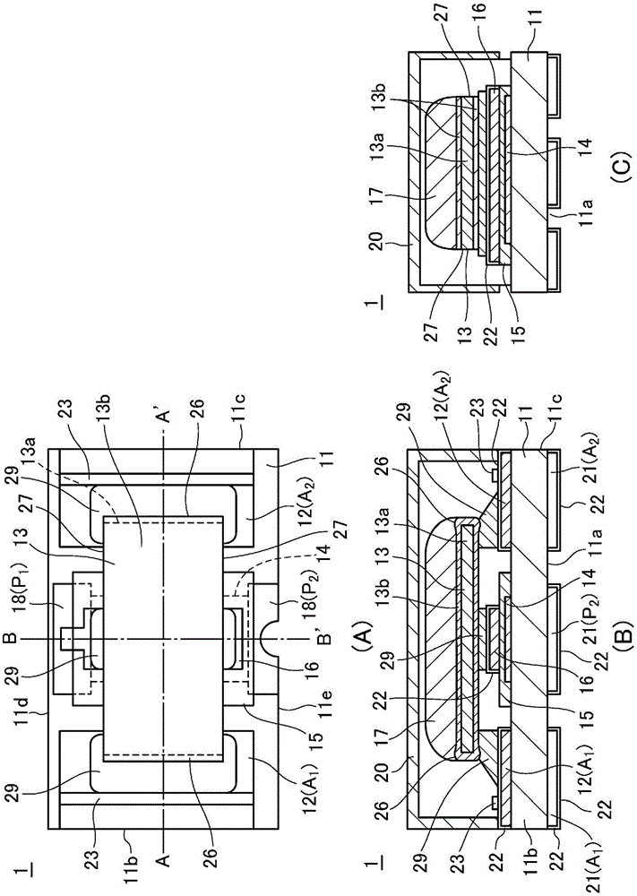
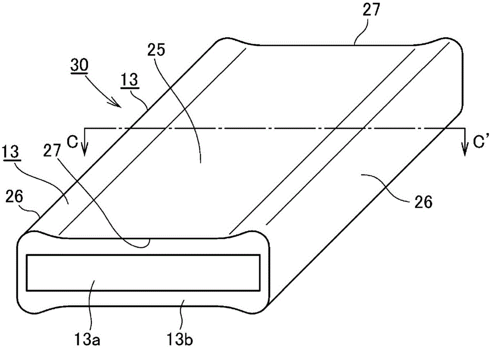
The present invention reduces a melting time without causing an increase in the man-hours for manufacturing a fusible conductor. The present invention is provided with an insulated substrate (11), a heating element (14), an insulating member (15) for covering the heating element (14), a heating element extraction electrode (16) electrically connected to the heating element (14), a first and a second electrode (12), and a fusible conductor (13) connected to the heating element extraction electrode (16) and through to the first and second electrodes (12), the fusible conductor (13) cutting, by melting, a current path between the first electrode (12)(A1) and the second electrode (12)(A2). The fusible conductor (13) is formed in greater thickness than a principal surface part (25), and has a pair of first side edge parts (26) facing each other and a pair of second side edge parts (27) facing each other and formed in lesser thickness than the first side edge parts, the second side edge parts (27) being disposed along the current path extending from the heating element extraction electrode (16) to the first and second electrodes (12).

Description

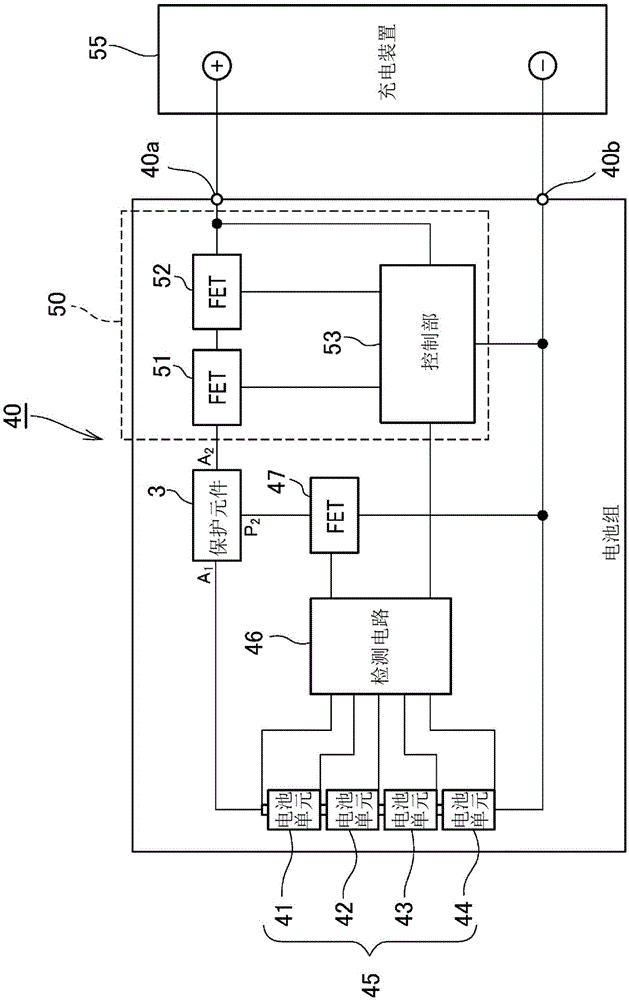
technical field [0001] The present invention relates to a protection element that cuts off a current path when abnormalities such as overcharge and overdischarge occur, and a protection circuit board on which the protection element is mounted. This application claims priority on the basis of Japanese Patent Application No. Japanese Patent Application No. 2013-171786 for which it applied in Japan on August 21, 2013, and this application is referred in this application. Background technique [0002] Most rechargeable and reusable secondary batteries are processed into battery packs and provided to users. Especially in lithium-ion secondary batteries with high gravimetric energy density, in order to ensure the safety of users and electronic equipment, several protection circuits such as overcharge protection and overdischarge protection are usually built into the battery pack, with A function to cut off the output of the battery pack. [0003] In this kind of protection eleme...

Claims


Application Information

Patent Timeline
Patent Type & Authority Applications(China)
IPC IPC(8): H01H37/76H01H85/08
CPCH01H85/06H01H85/08H01H2085/0283
Inventor 向幸市古内裕治柿沼亨藤畑贵史
Owner DEXERIALS CORP
Why Eureka
Try Eureka