
Aluminum rod pulling-out device used for aluminum rod roll

A pull-out device, aluminum rod technology, applied in the direction of wire drawing dies, etc., can solve the problems of reducing the work intensity of production staff, destroying the bonding state of aluminum rods, etc., and achieve the effect of reducing work intensity

Inactive Publication Date: 2016-04-13
JIANGSU HENGTONG ELECTRICAL SPECIAL WIRE CO LTD
View PDF11 Cites 0 Cited by
  • Summary
  • Abstract
  • Description
  • Claims
  • Application Information

AI Technical Summary

Problems solved by technology

[0008] The invention provides an aluminum rod pulling device for aluminum rod coils. The aluminum rod pulling device used for aluminum rod coils has the function of continuously generating vibrations, and solves the problems of crossing and bonding between aluminum rod rings and rings. , to destroy the bonded state of the aluminum rod, during the process of pulling out a single tie rod from the aluminum rod coil, the phenomenon of pulling out several turns at the same time is significantly reduced, and the work intensity of the production staff is reduced

Method used


Image

  • Aluminum rod pulling-out device used for aluminum rod roll
  • Aluminum rod pulling-out device used for aluminum rod roll

Examples


Embodiment 1

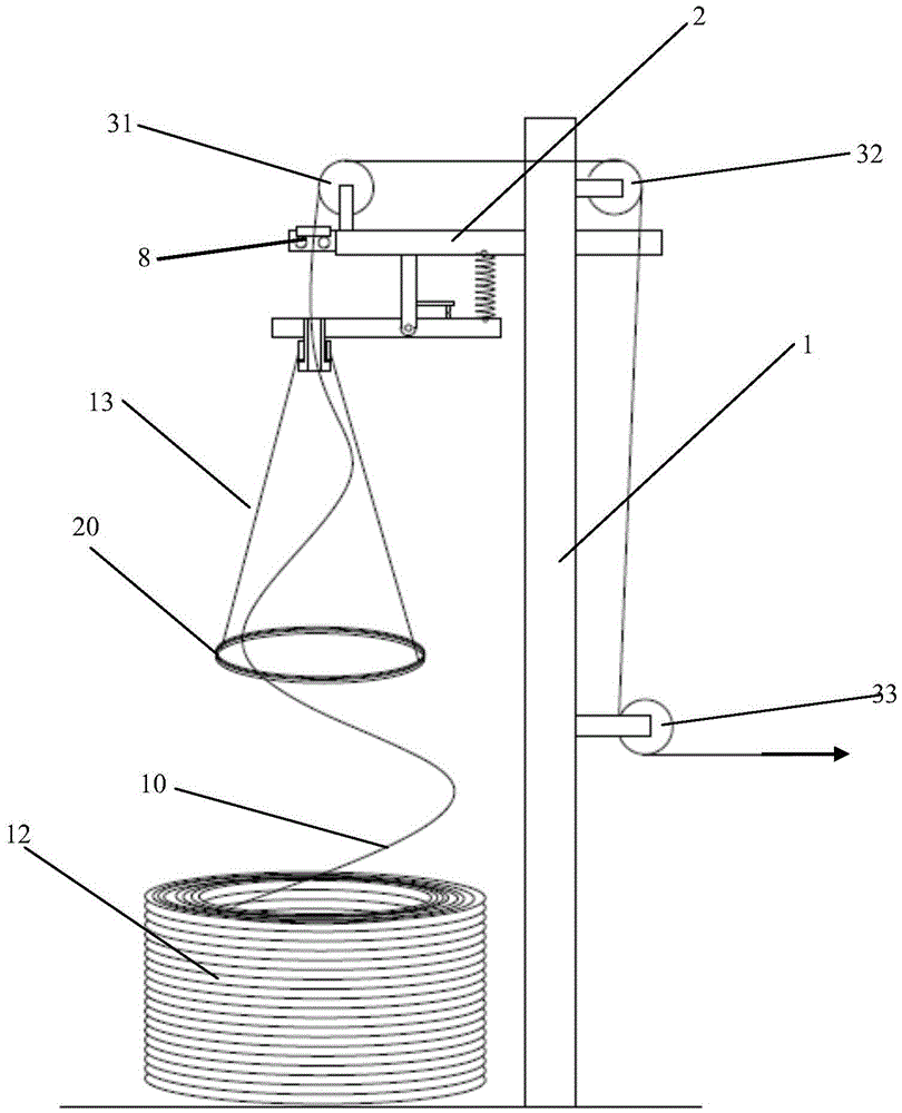
[0028] Embodiment 1: An aluminum rod pulling device for aluminum rod coils, including a column 1, a cross bar 2 and at least three guide wheel assemblies 3, the rear end of the cross bar 2 is fixed on the upper part of the column 1, the The first and second guide wheel assemblies 31 and 32 of the three guide wheel assemblies 3 are installed on both ends of the crossbar 2 respectively, and the third guide wheel assembly 33 of the three guide wheel assemblies 3 is installed in the middle of the column 1;

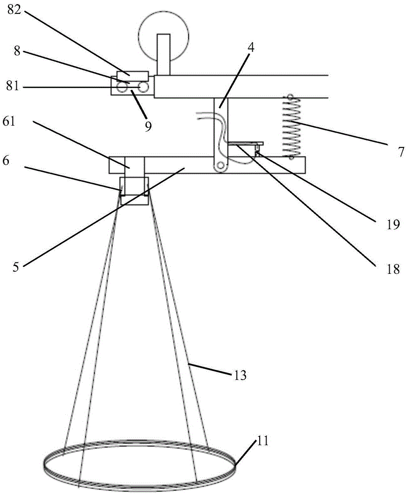
[0029] The crossbar 2 is fixed with a hanger 4 located below it, and the middle part of a plate body 5 is movably installed on the lower end of the crossbar 2, and the end of the plate body 5 away from the column 1 is equipped with a half mold 6. A spring 7 is arranged between the end of the plate body 5 close to the column 1 and the cross bar 2, a control switch for controlling the working state of the wire drawing machine is installed on the plate body, a detection contact is...

Embodiment 2

[0046] Embodiment 2: An aluminum rod pulling device for aluminum rod coils, including a column 1, a cross bar 2 and at least three guide wheel assemblies 3, the rear end of the cross bar 2 is fixed on the upper part of the column 1, the The first and second guide wheel assemblies 31 and 32 of the three guide wheel assemblies 3 are installed on both ends of the crossbar 2 respectively, and the third guide wheel assembly 33 of the three guide wheel assemblies 3 is installed in the middle of the column 1;

[0047] The crossbar 2 is fixed with a hanger 4 located below it, and the middle part of a plate body 5 is movably installed on the lower end of the crossbar 2, and the end of the plate body 5 away from the column 1 is equipped with a half mold 6. A spring 7 is arranged between the end of the plate body 5 close to the column 1 and the cross bar 2, a control switch 18 for controlling the working state of the wire drawing machine is installed on the plate body 5, and a detection c...


PUM

PropertyMeasurementUnit
diameteraaaaaaaaaa

Abstract

The invention discloses an aluminum rod pulling-out device used for an aluminum rod roll. A hanging frame located below a cross rod is fixed to the cross rod of the aluminum rod pulling-out device. The middle of a plate is movably installed at the lower end of the cross rod. A half die is installed at the end, away from a stand column, of the plate. A spring is arranged between the end, close to the stand column, of the plate and the cross rod. A regulating switch used for controlling the working state of a wire drawing machine is installed on the plate. A detection contact is installed on the hanging frame. A suspended circular ring is located between the half die and the aluminum rod roll, and the distance between the circular ring and the half die is at least one meter. The diameter of the circular ring is located between the inner diameter of the aluminum rod roll and the outer diameter of the half die. At least three connecting ropes which are arranged at equal intervals are connected between the circular ring and the half die. According to the aluminum rod pulling-out device used for the aluminum rod roll, the function of generating vibration continuously is achieved, the problems of crossing, sticking and the like generated between circles of aluminum rods are solved, the sticking state of the aluminum rods is broken, the single rods are pulled out of the aluminum rod roll one by one, the phenomena that several circles are pulled out at the same time are reduced, and the work intensity of production personnel is lowered.

Description

technical field [0001] The invention relates to an aluminum rod pulling device, in particular to an aluminum rod pulling device used for aluminum rod coils. Background technique [0002] The production process of aluminum wire drawing is: 2~3 tons of aluminum rods with a diameter of about 2m in rolls are placed flat on the ground, and a single aluminum rod with a diameter of 9.5mm~18mm is continuously pulled upwards and enters the first threading hole with a height of about 3m. Above the hole is the first guide wheel, which turns the aluminum rod. After the aluminum rod adjusts its direction through multiple guide wheels, it is introduced into the wire drawing device in parallel, and is drawn into a 1.0mm~5mm aluminum single wire through the mold and rollers. [0003] The 2-3 tons of rolled aluminum rods generally have 40-50 layers, and each layer has 120-160 turns. When the aluminum rod is coiled, it starts from the inner layer, and the circles of the aluminum rods are clo...

Claims


Application Information

Patent Timeline
Patent Type & Authority Applications(China)
IPC IPC(8): B21C1/20B21C1/34B21C3/02
CPCB21C1/20B21C1/34B21C3/02
Inventor 李名珍施娟吴松梅蔺亚强
Owner JIANGSU HENGTONG ELECTRICAL SPECIAL WIRE CO LTD
Learn More