led bulb lamp welding system

A technology of LED bulb lamp and welding system, applied in welding equipment, auxiliary devices, metal processing, etc., can solve the problems of low production efficiency, poor product quality stability and consistency, and high labor intensity.

Active Publication Date: 2017-07-14
SUZHOU JINGSHUO AUTOMATION EQUIP CO LTD
View PDF7 Cites 0 Cited by
  • Summary
  • Abstract
  • Description
  • Claims
  • Application Information

AI Technical Summary

Problems solved by technology

The existing LED bulb lamp welding is almost done manually or semi-automatically. Due to the different conditions of each manual operation, the product quality stability and consistency are poor, and after the production is completed, it must pass manual inspection; In addition, because a production line requires multiple workers to operate, not only the production efficiency is low, the labor intensity is high, but also the production cost and management difficulty are greatly increased.

Method used


Image

  • led bulb lamp welding system
  • led bulb lamp welding system
  • led bulb lamp welding system

Examples


Embodiment Construction

[0025] The present invention will be further described below in conjunction with the accompanying drawings and specific embodiments.

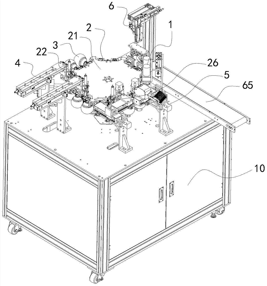
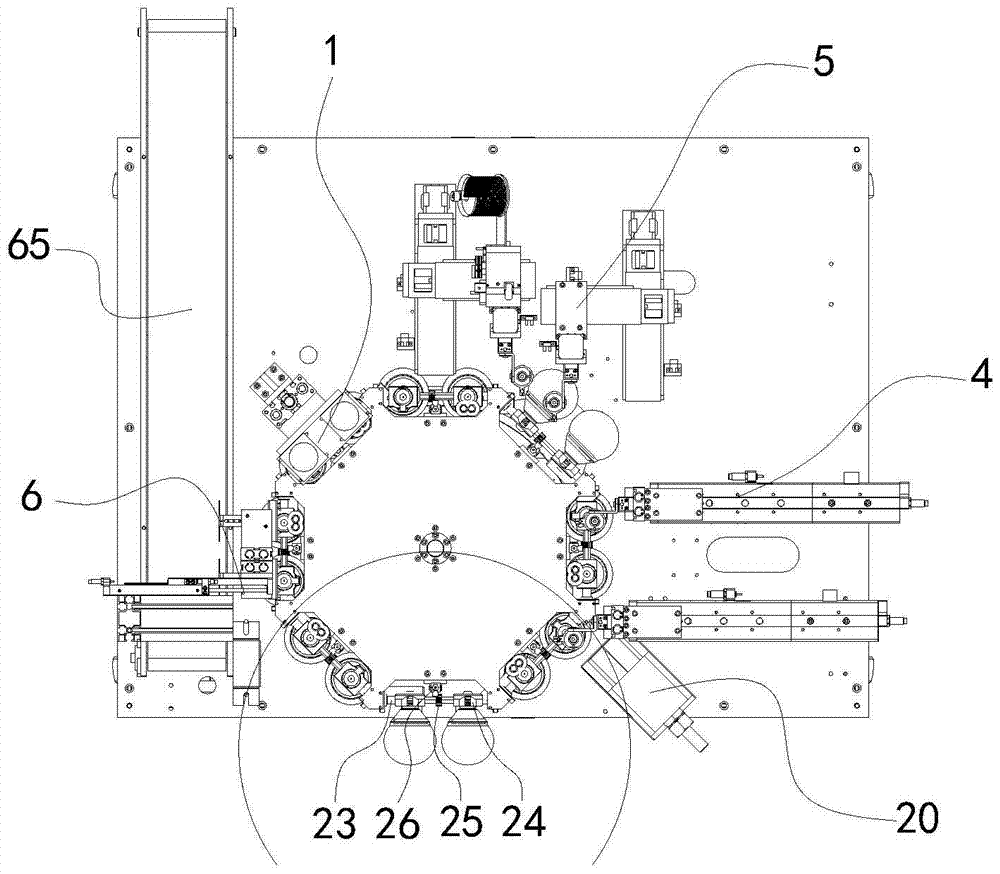
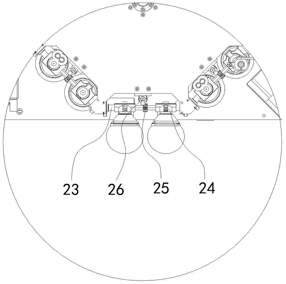
[0026] Such as Figure 1 to Figure 2 As shown, the LED bulb lamp welding system includes a frame 10. A turntable mechanism 2 is arranged on the frame 10. The turntable mechanism 2 includes a disc 21 and a turntable motor that drives the disc 21 to rotate. The disc 21 is arranged along the circumferential direction. There are multiple material levels, and each material level is respectively equipped with a rotating chuck mechanism 22 for fixing the bulb lamp. The outer side of the disc 21 is sequentially equipped with a side welding mechanism 4, a top welding mechanism 5, a rosin removal mechanism 1, and a feeding mechanism 6. The turntable motor drives the disc 21 to rotate, and the rotating chuck mechanism 22 is used to clamp the LED bulb lamp to be welded. The side welding mechanism 4 welds the sides of the LED bulb lamp, and the top welding ...


PUM


Abstract

The invention discloses an LED bulb lamp welding system which comprises a rack. A rotary disc mechanism is arranged on the rack. The rotary disc mechanism comprises a disc and a rotary disc motor driving the disc to rotate. A plurality of material positions are arranged on the disc in the circumferential direction, and rotating clamping head mechanisms used for fixing bulb lamps are arranged on the material positions respectively. The outer side of the disc is provided with a side face welding mechanism, a top welding mechanism, a rosin removing mechanism and a discharging mechanism in sequence. The rotary disc motor drives the disc to rotate. The rotating clamping head mechanisms are used for clamping the LED bulb lamps to be welded. The feeding mechanism conducts feeding. The side face welding mechanism is used for welding the side faces of the LED bulb lamps. The top welding mechanism is used for welding the tops of the LED bulb lamps. The rosin removing mechanism is used for removing rosin on the tops of the LED bulb lamps. The discharging mechanism is used for performing discharging after rosin is removed, and automatic welding and rosin removing of the LED bulb lamps are achieved.

Description

technical field [0001] The invention relates to the field of LED bulb lamp production, in particular to an LED bulb lamp welding system. Background technique [0002] Because the internal light source of LED bulbs is LED lamp beads, it has the advantages of energy saving and environmental protection, long service life, uniform light guide and no light damage, etc., thus becoming one of the most used light bulbs by citizens. [0003] The traditional LED bulb lamp processing and assembly process is cumbersome, including the following steps: 1. Manually put the product into the fixture to weld the edge line; 2. Manually top-weld the product with the welded sideline inside the fixture; Good products remove top welding rosin; 4. Manually remove side welding rosin. The existing LED bulb lamp welding is almost done manually or semi-automatically. Due to the different conditions of each manual operation, the product quality stability and consistency are poor, and after the producti...

Claims


Application Information

Patent Timeline
Patent Type & Authority Patents(China)
IPC IPC(8): B23K3/00B23K3/08
CPCB23K3/00B23K3/08
Inventor 范建群
Owner SUZHOU JINGSHUO AUTOMATION EQUIP CO LTD
Why Eureka
Try Eureka