Automatic welding device and welding method

An automatic welding and device pairing technology, applied in auxiliary devices, welding equipment, welding equipment, etc., can solve the problems of difficulty in seamless connection and inconvenience in actual use, and achieve the effect of extending welding distance, ensuring welding accuracy and reducing costs.

Active Publication Date: 2016-04-13
SHENZHEN RILAND IND
View PDF9 Cites 8 Cited by
  • Summary
  • Abstract
  • Description
  • Claims
  • Application Information

AI Technical Summary

Problems solved by technology

The length of a single mechanical track is generally limited to about 2-3m, so for long straight welds, multiple mechanical tracks are required to connect, which is very inconvenient in actual use, and the seamless connection between each track and the mechanical track and weld are guaranteed Accurate parallelism is also very difficult, usually one or more trial runs are required to verify and adjust the error between the trolley walking mechanical track and the weld seam

Method used


Image

  • Automatic welding device and welding method
  • Automatic welding device and welding method

Examples


Embodiment Construction

[0023] The following will clearly and completely describe the technical solutions in the embodiments of the present invention with reference to the accompanying drawings in the embodiments of the present invention. Obviously, the described embodiments are only part of the embodiments of the present invention, not all of them. Based on the embodiments of the present invention, all other embodiments obtained by persons of ordinary skill in the art without creative efforts fall within the protection scope of the present invention.

[0024] It should be noted that all directional indications (such as up, down, left, right, front, back...) in the embodiments of the present invention are only used to explain the relationship between the components in a certain posture (as shown in the accompanying drawings). Relative positional relationship, movement conditions, etc., if the specific posture changes, the directional indication will also change accordingly.

[0025] In addition, in t...


PUM

PropertyMeasurementUnit
lengthaaaaaaaaaa

Abstract

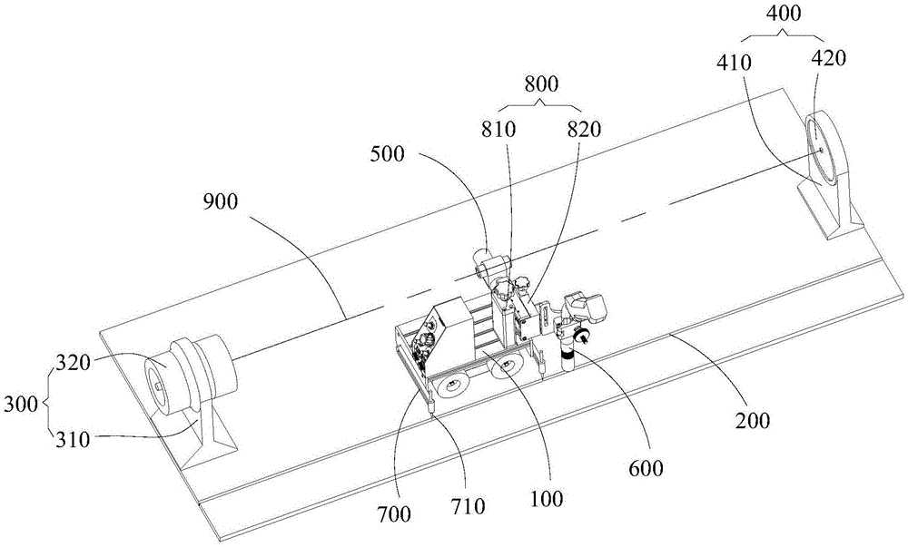
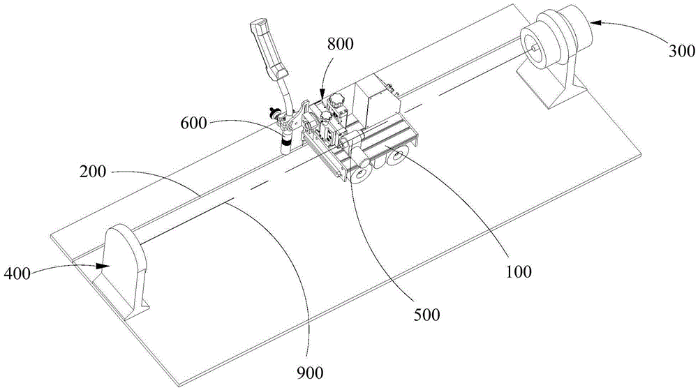
The invention discloses an automatic welding device and a welding method. The device and method are used for welding a long straight weld joint. The automatic welding device comprises a welding trolley. The welding trolley walks on one side of the weld joint. The automatic welding device is characterized by further comprising a laser beam transmitting device and a correction device, the laser beam transmitting device and the correction device are arranged at the two ends of the same side of the weld joint respectively, laser beams transmitted through the laser beam transmitting device are corrected through the correction device relative to the weld joint, the welding trolley is provided with a laser position sensor and a position adjusting mechanism, and the laser position sensor induces the laser beams and controls the position adjusting mechanism to adjust the welding route of the welding trolley. By the adoption of the automatic laser welding device, no walking mechanical rail needs to be additionally arranged for the welding trolley in the welding process of the long straight weld joint, the welding distance is prolonged, and welding cost is reduced.

Description

technical field [0001] The invention relates to the technical field of welding machines, in particular to a laser-guided automatic welding device and a welding method. Background technique [0002] At present, for the automatic welding of welding seams, the welding trolley is usually used as the movement trajectory control mechanism of the welding torch. In order to ensure that the walking trajectory of the welding trolley is consistent with the welding seam, a mechanical track that is precisely parallel to the welding seam needs to be laid in advance. The length of a single mechanical track is generally limited to about 2-3m, so for long straight welds, multiple mechanical tracks are required to connect, which is very inconvenient in actual use, and the seamless connection between each track and the mechanical track and weld are guaranteed Accurate parallelism is also very difficult, usually one or more trial runs are required to verify and adjust the error between the trol...

Claims


Application Information

Patent Timeline
Patent Type & Authority Applications(China)
IPC IPC(8): B23K37/00B23K37/02B23K9/127
CPCB23K9/1274B23K37/00B23K37/0294
Inventor 耿正王巍兰美云
Owner SHENZHEN RILAND IND
Why Eureka
Try Eureka