
Power source switching mechanism

A power source switching and power technology, applied in the field of packaging equipment parts, can solve problems such as double-layer boxing, and achieve the effect of promoting mass production, saving equipment and improving utilization.

Active Publication Date: 2016-04-13
JOYEA CORP
View PDF4 Cites 0 Cited by
  • Summary
  • Abstract
  • Description
  • Claims
  • Application Information

AI Technical Summary

Problems solved by technology

At present, many medicines, health products, and food manufacturers produce products that are packaged in strips (STICK strip bag independent unit) and put into packaging boxes for sale; currently, there are two commonly used states for strip packaging: one It is to pack single-layer strips; another is to pack double-layer strips; these two states cannot be switched on one device, and traditional equipment is only for single-layer cartoning. Either only for double boxed

Method used


Image

  • Power source switching mechanism
  • Power source switching mechanism
  • Power source switching mechanism

Examples


Embodiment Construction

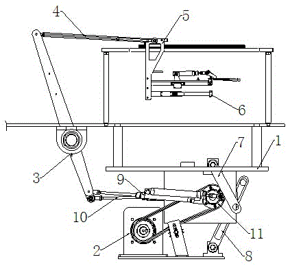
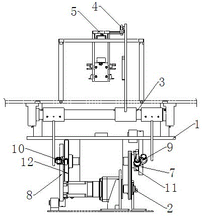
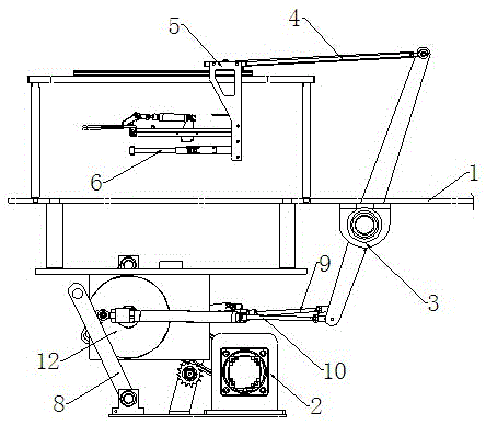
[0011] Depend on figure 1 It is known that a power source switching mechanism consists of a frame 1, a power assembly 2, a push handle swing rod 3, a connecting rod 4, a slider 5, an executive push handle 6, a power swing rod I7, a power swing rod II8, and a combined cylinder connecting rod I9 Composed of combined cylinder connecting rod II 10, the bottom of the frame 1 is equipped with a power assembly 2, which is connected to the driven mechanism on the frame 1, with a small wheel 11 at one end of the driven mechanism and a large wheel 12 at the other end; The upper end of the power swing rod I7 is flexibly connected to the frame 1, the lower end of the power swing rod I7 is flexibly connected to the combined cylinder connecting rod I9, and a chute is provided in the power swing rod I7 to be flexibly connected to the small wheel 11; the power swing rod II8 The lower end is movably connected to the bottom of the frame 1, the upper end of the power swing rod Ⅱ8 is movably conn...


PUM


Abstract

The invention discloses a power source switching mechanism. The power source switching mechanism comprises a rack (1), a power component (2), a pushing hand oscillating bar (3), a connecting rod (4), a sliding block (5), an executive pushing hand (6), a power oscillating bar I (7), a power oscillating bar II (8), a combined cylinder connecting rod I (9) and a combined cylinder connecting rod II (10), and is characterized in that during working, the combined cylinder connecting rod I (9) and the combined cylinder connecting rod II (10) are in an aerated state and form rigid bodies; when not aerated, the combined cylinder connecting rod I (9) and the combined cylinder connecting rod II (10) are telescopic bodies and are in a non-working state; and the working states of the combined cylinder connecting rod I (9) and the combined cylinder connecting rod II (10) can be mutually switched. According to the power source switching mechanism, through switching the combined cylinder connecting rod I (9) and the combined cylinder connecting rod II (10) for use, the pushing and arrangement of double-layer bar stocks and single-layer bar stocks are respectively achieved, the utilization rate of the device is greatly increased, the production efficiency is greatly improved, and the large-batch production and popularization are facilitated.

Description

technical field [0001] The invention relates to the technical field of packaging equipment components, in particular to a power source switching mechanism. Background technique [0002] In the highly competitive market environment, many products appear in the form of strip bags of materials such as granules and powders, which are widely used due to their advantages such as easy portability. At present, many medicines, health products, and food manufacturers produce products that are packaged in strips (STICK strip bag independent unit) and put into packaging boxes for sale; currently, there are two commonly used states for strip packaging: one It is to pack single-layer strips; another is to pack double-layer strips; these two states cannot be switched on one device, and traditional equipment is only for single-layer cartoning. Either it is only for double boxing. Contents of the invention [0003] According to the above-mentioned defects, the purpose of the present inve...

Claims


Application Information

Patent Timeline
Patent Type & Authority Applications(China)
IPC IPC(8): B65B65/02
CPCB65B65/02
Inventor 张小平殷祥根
Owner JOYEA CORP
Learn More