System plugging and draining structure for tunnel leakage treatment

A technology for drainage structures and tunnels, applied in drainage, tunnels, tunnel linings, etc., can solve problems such as failure to effectively cut off seepage channels, failure to effectively cut off groundwater, and unsatisfactory effects, and achieve good drainage effects and easy pipelines. Conservation, technical effect with remarkable effect

Inactive Publication Date: 2016-04-13
WUHAN MUNICIPAL ENG DESIGN & RES INST
View PDF7 Cites 11 Cited by
  • Summary
  • Abstract
  • Description
  • Claims
  • Application Information

AI Technical Summary

Problems solved by technology

Grouting in the tunnel is to seal the source groundwater in the surrounding rock outside the tunnel lining by forming a water stop ring of a certain thickness on the outside of the tunnel lining, but it cannot effectively block the seepage channel, so the effect of using this method is It is often not ideal; at the same time, due to

Method used


Image

  • System plugging and draining structure for tunnel leakage treatment
  • System plugging and draining structure for tunnel leakage treatment
  • System plugging and draining structure for tunnel leakage treatment

Examples


Example Embodiment

[0019] Now, in conjunction with the drawings, we will further explain how the present invention is implemented:

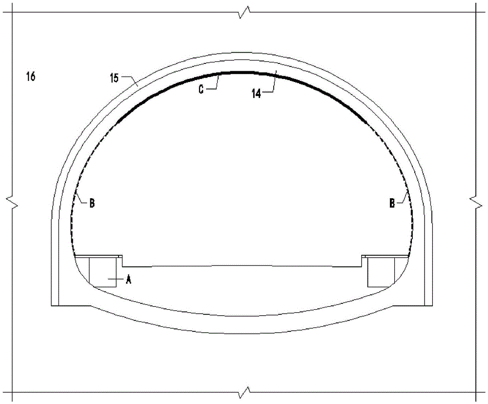
[0020] The existing tunnel structure can be summarized as follows: from bottom to top, there are pipe trench part A, circumferential side wall part B, and arch part C; from the inside to the outside, they are the secondary lining layer 14, the primary lining layer 15, and the surrounding Rock 16, such as figure 1 Shown.

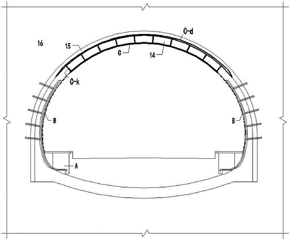
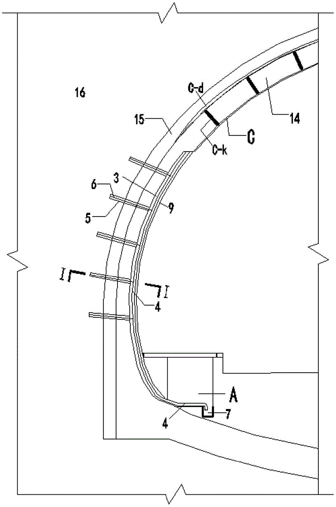
[0021] The present invention is a system leakage stoppage and drainage structure for tunnel leakage treatment, which includes a leakage stoppage layer Cd at a tunnel arch part C and a built-in drainage pipeline Bp at a tunnel circumferential side wall part. The tunnel arch part C The plugging layer Cd is grouted inward through the grouting hole Ck opened in the arched part of the tunnel, and a stable grouting plugging layer is formed between the secondary lining layer 14 and the primary lining layer 15 of the arched part of the tunnel ,Such as figure...


PUM


Abstract

The invention provides a system plugging and draining structure for tunnel leakage treatment, and belongs to the technical field of tunnel maintenance. The system plugging and draining structure for tunnel leakage treatment comprises a grouting plugging layer between a secondary lining layer of the arch-shaped part of a tunnel and a primary lining layer and a built-in drainage pipeline of the side wall part in the circumferential direction of the tunnel; on one hand, arch-shaped leakage source water is blocked outside a secondary lining, and treatment is conducted on leakage from the source; on the other hand, the drainage pipeline is arranged on the circular side wall part in the circumferential direction, and the leakage source water is discharged out of the tunnel through the drainage pipeline. According to the system plugging and draining structure for tunnel leakage treatment, existing structural facilities in the tunnel are fully utilized, safety and use of the tunnel are not affected, the drain path is definite, the draining effect is good, plugging and discharging are combined, comprehensive treatment is achieved, pipeline maintenance in later period is facilitated, effective system treatment on tunnel leakage is achieved, and the technical effect is significant.

Description

Technical field [0001] The present invention is a system leakage stopping and drainage structure used for tunnel leakage treatment, belonging to the technical field of tunnel maintenance. Background technique [0002] Whether at home or abroad, most tunnels have different degrees of disease. The main types of tunnel diseases are water damage, frost damage, lining damage and lining erosion. The most common form of disease is water damage, which is manifested in different degrees of tunnels. The so-called “ten tunnels and nine leaks” reflect the frequent flooding of tunnels. Among the leakage phenomena of tunnels, the leakage of water from construction joints and deformation joints is the most common in the inner circumferential direction; relevant data show that it accounts for more than 60% of the total leakage of the tunnel. The phenomenon of "must leak, seamless and no leak", after the tunnel leaks, it will increase the impact on the safe operation of the tunnel, and even enda...

Claims


Application Information

Patent Timeline
IPC IPC(8): E21D11/38E21F16/02
CPCE21D11/38E21F16/02
Inventor 胡云华和礼红陈建斌蒋乐姚华龚哲
Owner WUHAN MUNICIPAL ENG DESIGN & RES INST
Why Eureka
Try Eureka