Supercharge Your Innovation With Domain-Expert AI Agents!

Oil retaining components and compressors

A compressor and a technology in compressors, applied in the field of compressors, can solve the problems of high production cost, high manufacturing precision requirements, complex oil blocking cap structure, etc., and achieve the effect of reducing manufacturing precision requirements and reducing production costs.

Active Publication Date: 2018-09-25
GREE ELECTRIC APPLIANCES INC +1
View PDF8 Cites 0 Cited by
  • Summary
  • Abstract
  • Description
  • Claims
  • Application Information

AI Technical Summary

Problems solved by technology

[0003] The embodiment of the present invention provides an oil retaining assembly and a compressor to solve the complex structure of the oil retaining cap in the prior art, which requires high manufacturing precision and high production cost

Method used


Image

  • Oil retaining components and compressors
  • Oil retaining components and compressors
  • Oil retaining components and compressors

Examples


Embodiment Construction

[0020] The present invention will be described in further detail below in conjunction with the accompanying drawings and specific embodiments, but not as a limitation of the present invention.

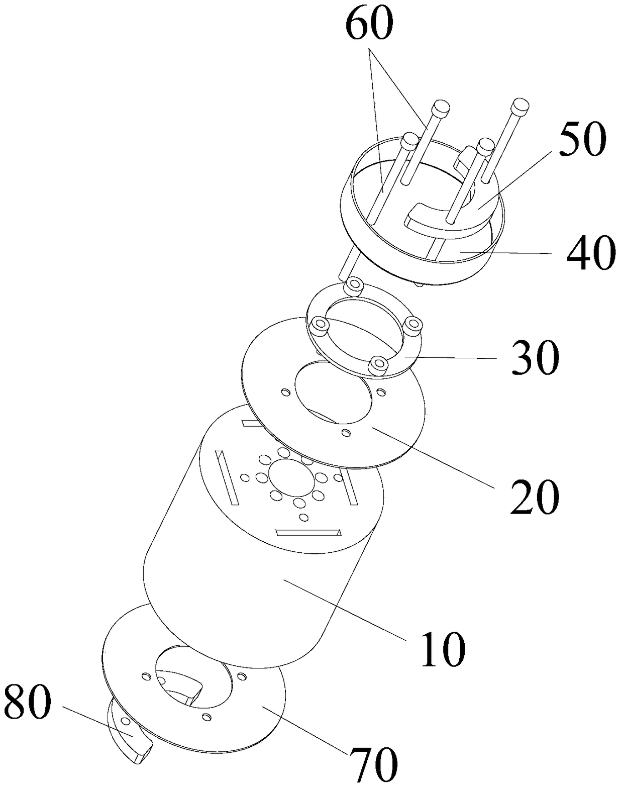
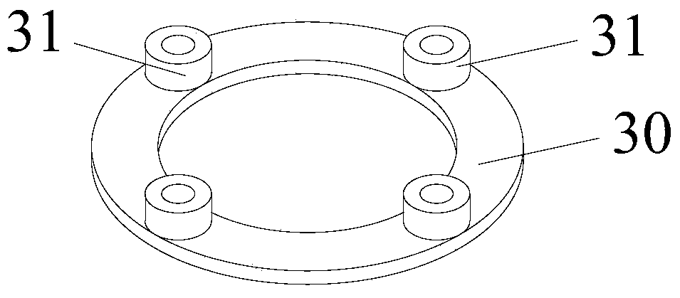
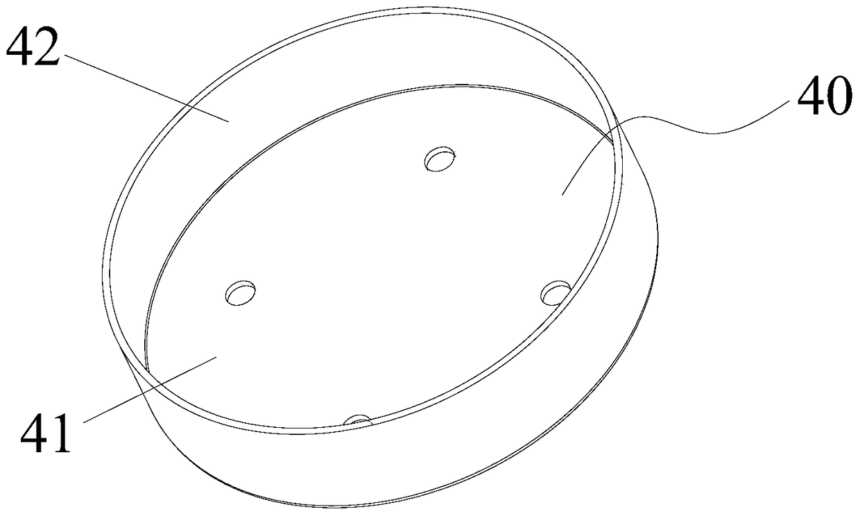
[0021] see Figure 1 to Figure 3 As shown, according to the embodiment of the present invention, an oil retaining assembly is provided, which is arranged in a compressor. The compressor has a rotor core 10, and the oil retaining assembly has an upper baffle plate 20, a mounting seat 30 and an oil retaining cap 40, The upper baffle 20 is arranged at one end of the rotor core 10, and the mounting seat 30 is connected to the upper baffle 20. The mounting seat 30 has a hollow area avoiding the passage hole on the rotor core 10, and the mounting seat 30 has a plurality of protruding mounting holes. The step 31 , the installation step 31 is located on the side of the installation base 30 away from the upper baffle 20 . The oil deflector cap 40 is connected to the installation steps 31 , and...


PUM


Abstract

The invention discloses an oil baffle assembly and a compressor. The oil baffle assembly comprises an upper baffle, a mounting seat and an oil baffle cap. The upper baffle is arranged at one end of a rotor iron core. The mounting seat is connected to the upper baffle and provided with a hollow area avoiding a through-flow hole in the rotor iron core, the mounting seat is provided with a plurality of protruding mounting steps, and the mounting steps are located on the side, deviating from the upper baffle, of the mounting seat. The oil baffle cap is connected to the mounting steps, and a clearance allowing refrigerant oil to circulate is formed among the oil baffle cap and the mounting steps. According to the oil baffle assembly and the compressor, the problems that in the prior art, an oil baffle cap is complex in structure, the requirement for manufacturing precision is high, and production cost is high are effectively solved.

Description

technical field [0001] The invention relates to the technical field of compressors, in particular to an oil retaining assembly and a compressor. Background technique [0002] In the prior art, the rotor iron core of the compressor (such as an inverter compressor) has flow holes inside, and the refrigerated oil is blocked by the oil deflector after passing through the flow holes, and flows back to the bottom of the compressor through the gap between the stator and the rotor or the trimming of the stator , To achieve oil circuit circulation, a certain gap needs to be left between the oil deflector cap and the flow hole to facilitate the spraying of refrigerated oil to the surroundings. However, the oil retaining cap needs to have an interference fit with the crankshaft, so that the oil retaining cap needs to be machined with a shaft hole that fits the crankshaft in an interference fit, and the shaft hole has high precision requirements, which leads to a complex structure of th...

Claims


Application Information

Patent Timeline
Patent Type & Authority Patents(China)
IPC IPC(8): F04C29/00
CPCF04C29/00
Inventor 刘锋陈彬
Owner GREE ELECTRIC APPLIANCES INC
Features
  • R&D
  • Intellectual Property
  • Life Sciences
  • Materials
  • Tech Scout
  • Unparalleled Data Quality
  • Higher Quality Content
  • 60% Fewer Hallucinations
Learn More