A steering control valve

A technology of steering control and reversing valve, applied in the direction of fluid pressure actuators, servo motor components, mechanical equipment, etc., to achieve the effects of good maintainability, wide application range, and low cost

Active Publication Date: 2017-06-16
ZHENGZHOU YUTONG HEAVY IND
View PDF10 Cites 0 Cited by
  • Summary
  • Abstract
  • Description
  • Claims
  • Application Information

AI Technical Summary

Problems solved by technology

[0002] With the large-scale and high-speed construction machinery and equipment, high-power, energy-saving and intelligent steering hydraulic systems have become the primary issues for current development and application. The corresponding hydraulic system working pressure is also increasing rapidly. The system is gradually being replaced. Therefore, as a key component of the hydraulic system, it can no longer meet the new needs and needs to be upgraded.

Method used


Image

  • A steering control valve

Examples


Embodiment Construction

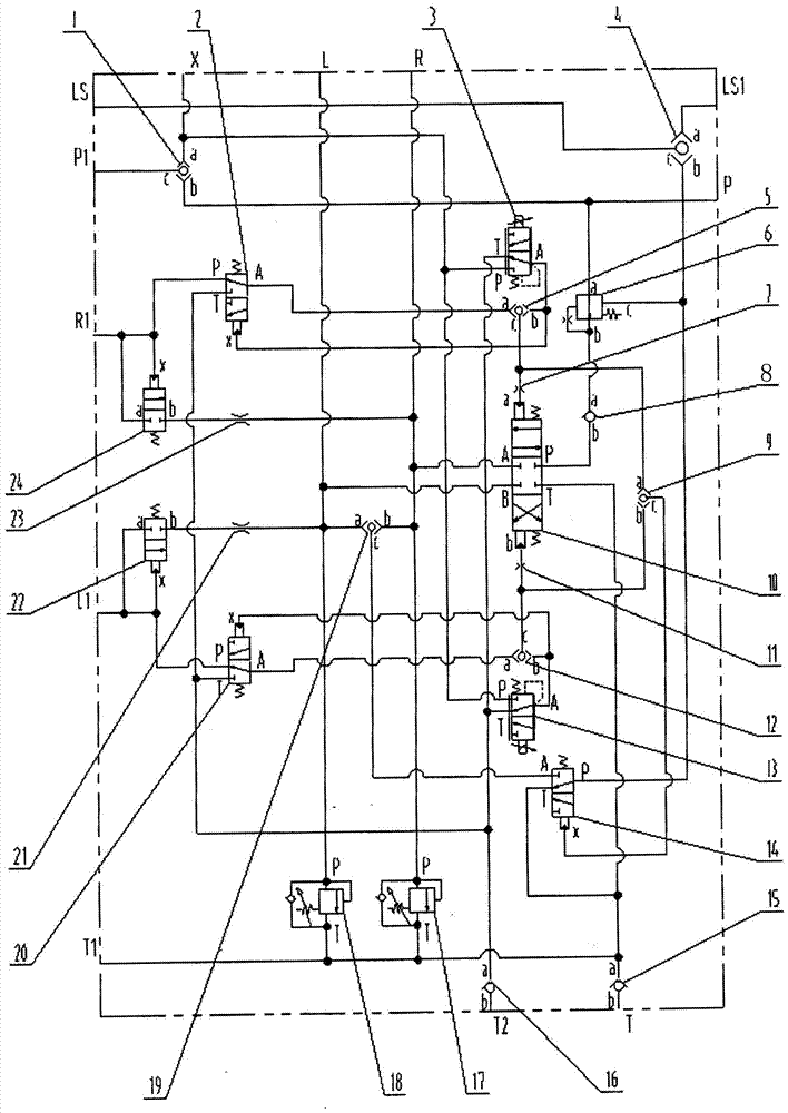
[0016] Such as figure 1 As shown, the steering control valve of the present invention includes a first oil port P, a second oil port T, a third oil port T1, a fourth oil port T2, a fifth oil port R, a sixth oil port L, a seventh oil port Valve body of oil port R1, eighth oil port L1, ninth oil port P1, tenth oil port LS, eleventh oil port LS1, twelfth oil port X, shuttle valve I1 installed in the valve body, two-position Three-way hydraulic control directional valve Ⅰ2, two-position three-way electric proportional directional valve Ⅰ3, shuttle valve Ⅱ4, shuttle valve Ⅲ5, compensation valve 6, damping Ⅰ7, one-way valve Ⅰ8, shuttle valve Ⅳ9, three-position 4-way hydraulic control directional control valve Directional valve 10, damping Ⅱ11, shuttle valve Ⅴ12, two-position three-way electric proportional directional valve Ⅱ13, two-position three-way hydraulic control directional valve Ⅱ14, one-way valve Ⅱ15, one-way valve Ⅲ16, oil supplement overload valve Ⅰ17, oil supplement Ove...


PUM


Abstract

A steering control valve comprises a valve body with a first oil port, a second oil port, a third oil port, a fourth oil port, a fifth oil port, a sixth oil port, a seventh oil port, an eighth oil port, a ninth oil port, a tenth oil port, an eleventh oil port and a twelfth oil port, a shuttle valve I mounted in the valve body, a two-position three-way hydraulic operated reversing valve I, a two-position three-way electric proportional reversing valve I, a shuttle valve II, a shuttle valve III, a compensation valve, a damper I, a one-way valve I, a shuttle valve IV, a three-position four-way hydraulic operated reversing valve, a damper II, a shuttle valve V, a two-position three-way electric proportional reversing valve II, a two-position three-way hydraulic operated reversing valve II, a one-way valve II, a one-way valve III, an oil-supplementing overload valve, an oil-supplementing overload valve, a shuttle valve VI, a two-position three-way hydraulic operated reversing valve III, a damper III, a two-position two-way hydraulic operated reversing valve I, a damper IV and a two-position two-way hydraulic operated reversing valve II. The steering control valve adopts double control of full hydraulic control and electric-hydraulic proportional line control, realizes double control in the aspect of safety, has a manpower emergency steering function and can improve the operability and reduce the operation intensity of a driver.

Description

technical field [0001] The patent of the present invention relates to hydraulic control technology fields such as engineering machinery and mining machinery, and in particular relates to a steering control valve. Background technique [0002] With the large-scale and high-speed construction machinery and equipment, high-power, energy-saving and intelligent steering hydraulic systems have become the primary issues for current development and application. The corresponding hydraulic system working pressure is also increasing rapidly. The system is gradually being replaced. Therefore, as a key component of the hydraulic system, it can no longer meet the new needs and needs to be upgraded. Contents of the invention [0003] The purpose of the present invention is to provide a steering control valve to meet the needs of upgrading and replacement, aiming at the deficiencies in the prior art. The steering control valve of the present invention has dual control of full hydraulic ...

Claims


Application Information

Patent Timeline
Patent Type & Authority Patents(China)
IPC IPC(8): F15B13/02
CPCF15B13/02
Inventor 杨虎堵利宾高利斌李永章段俊锋张增
Owner ZHENGZHOU YUTONG HEAVY IND
Why Eureka
Try Eureka