
Electric magnet for actuating mechanism magnetic valve of electronic control system of automobile

A technology of electric control system and actuator, applied in the direction of electromagnets with armatures, electromagnets, valve details, etc., can solve the problems of unsatisfactory proportional characteristics of electromagnets, slow dynamic response, low manufacturing cost, etc., and achieve simple structure, The effect of fast dynamic response and low manufacturing cost

Active Publication Date: 2013-08-21
MIANYANG FULIN PRECISION MACHINING
View PDF7 Cites 0 Cited by
  • Summary
  • Abstract
  • Description
  • Claims
  • Application Information

AI Technical Summary

Problems solved by technology

[0003] The purpose of this invention is to solve the problems of unsatisfactory proportional characteristics, slow dynamic response and high production cost of existing electromagnets, and provide an electromagnetic Electromagnet for valve, the electromagnet has simple structure, good proportional characteristics, fast dynamic response and low manufacturing cost

Method used


Image

  • Electric magnet for actuating mechanism magnetic valve of electronic control system of automobile
  • Electric magnet for actuating mechanism magnetic valve of electronic control system of automobile
  • Electric magnet for actuating mechanism magnetic valve of electronic control system of automobile

Examples


Embodiment Construction

[0039] The present invention will be further described through the embodiments below in conjunction with the accompanying drawings.

[0040] preferred embodiment

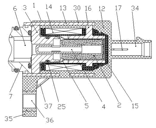
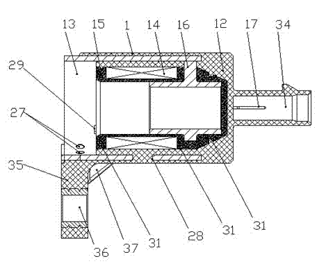
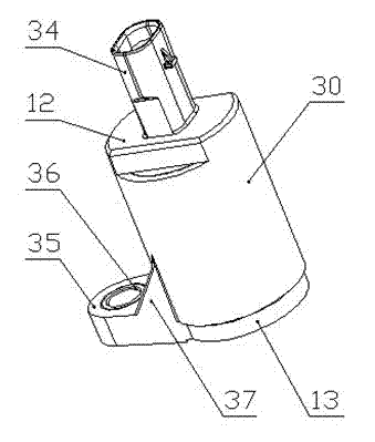
[0041] An electromagnet for a solenoid valve of an actuator of an automobile electronic control system, such as figure 1 As shown, it includes an electromagnetic solenoid, a magnetic core, a pole piece, a push rod and a guide sleeve. The front end of the electromagnetic solenoid is provided with a solenoid valve spool, the spool is arranged in the valve sleeve, and the cup-shaped guide sleeve is arranged in the electromagnetic valve. In the inner hole of the solenoid, the top of the guide sleeve faces the side of the valve core, the magnetic core is hollow cylindrical, and is arranged on the side near the bottom of the guide sleeve, the push rod is a hollow cylindrical structure with one end open, and the open end is inserted into the magnetic core , the middle part of the push rod is provided with a radi...


PUM


Abstract

The invention provides an electric magnet for an actuating mechanism magnetic valve of an electronic control system of an automobile, relates to an electric magnet device of a magnetic valve, and aims at solving the problem that an existing electric magnet is not ideal in proportional characteristic, slow in dynamic response and high in manufacture cost. The electric magnet comprises an electromagnetic solenoid, a magnetic core, a pole shoe, a push rod and a guide sleeve. The guide sleeve is arranged in an inner hole of the electromagnetic solenoid, the magnetic core is arranged on one side close to the bottom end in the guide sleeve, and one end of the push rod is inserted into the magnetic core. A branch type structure is radially distributed in the middle of the push rod, a through hole is arranged on a push rod wall at the front end of the branch type structure, the rear end face of the branch type structure is tightly adhered to the front end face of the magnetic core, and the pole shoe comprises a large-diameter disc end and a small-diameter small cylindrical end, the front end of the push rod is inserted into the pole shoe, the small cylindrical end is arranged in the guidesleeve, an excircle of the small cylindrical end is matched with an inner hole of the guide sleeve, the top end of the small cylindrical end and the front end face of the magnetic core are separated through the branch type structure, and the front end face of the disc end is connected with a valve sleeve. The electric magnet is simple in structure, good in proportional characteristic, quick in dynamic response and low in manufacture cost.

Description

technical field [0001] The invention relates to an electromagnet device for a solenoid valve, in particular to an electromagnet for a solenoid valve of an actuator of an automobile electric control system. Background technique [0002] With the improvement of living standards and the development of automobile technology, people have higher and higher requirements for automobile handling, comfort, energy saving and environmental protection, which has prompted a large number of applications of automobile electronic control systems and rapid technological progress. Most of the execution needs solenoid valves to complete. The application of solenoid valves in automobiles will gradually increase. The execution accuracy and speed of solenoid valves are directly related to the performance of automobiles. Electromagnets are the core components of solenoid valves, which convert electrical signals into The kinetic energy that pushes the spool to work. In the high-precision proportiona...

Claims


Application Information

Patent Timeline
Patent Type & Authority Patents(China)
IPC IPC(8): H01F7/08F16K31/06
Inventor 谭建伟阳宇向明朗陈兵
Owner MIANYANG FULIN PRECISION MACHINING
Learn More