Linear sliding rail with six columns of rolling balls

A linear slide, ball type technology, applied in the direction of linear motion bearings, bearings, shafts and bearings, etc., can solve the problem of not being able to significantly improve the load capacity, poor load capacity, and poor ability to withstand side loads. , to achieve the effect of improving production efficiency and economic benefits, and simplifying processing procedures

Active Publication Date: 2016-04-13
HIWIN TECH
View PDF7 Cites 1 Cited by
  • Summary
  • Abstract
  • Description
  • Claims
  • Application Information

AI Technical Summary

Problems solved by technology

[0002] Linear ball slide rail is an important linear transmission device. It has high efficiency and high precision transmission characteristics, so it is widely used in various transport machinery. One of the key considerations in the selection of linear ball slide rail is its reason The static rated load that can be borne includes the static rated load in the downward direction, the upward direction and the lateral direction, and the static rated load that a general linear ball slide can withstand is positively correlated with the number of ball rows and the square of the ball diameter, so The industry usually increases the static rated load capacity by increasing the diameter of the ball or increasing the number of ball rows; however, the demand for the static rated load of machinery continues to increase, and the static rated load of the general linear ball slide is still insufficient at present, and it needs to be further improved. promote
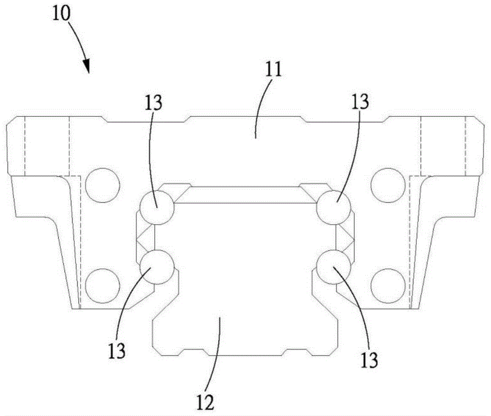
[0003] like figure 1 Shown is the linear slide rail 10 of Japanese Patent Application Laid-Open No. Hei 07-035136, which mainly includes a slide block 11 slidably covered on a slide rail 12, and four slide rails 12 and the slide block 11 are arranged between 13 rows of balls, the linear slide rail 10 mainly increases the number of rows from the general two rows to four rows of balls 13, the four rows of balls 13 are symmetrically located on both sides of the slide rail 12, by increasing the number of 13 rows of balls to improve The static rated load that the linear slide rail 10 can withstand; however, from the configuration of the four rows of balls 13 of the linear slide rail 10, the four rows of balls 13 of the linear slide rail 10 are all arc-shaped two-point 45° -45° contact mode, that is, the contact angle between all the balls and the contacting rolling groove is 45°. Under this contact angle configuration mode, the load capacity in the downward direction, upward direction and lateral direction can be provided evenly; and The tooth shape coefficient of the linear slide rail 10 is also configured to be exactly the same tooth shape coefficient, so that the structure of the overall linear slide rail 10 can completely and uniformly provide the load capacity in the downward direction, the upward direction and the lateral direction, but, for special The mechanical structure that requires higher downward pressure direction, upward direction and lateral load, the static rated load of this design still cannot meet the requirements
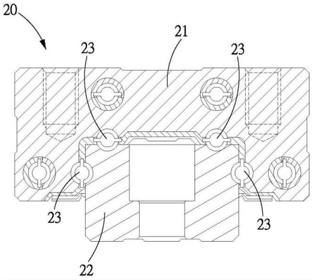
[0004] like figure 2 Shown is the linear slide rail 20 of U.S. No. US6132093 patent, and this is a kind of known technology that strengthens its static rated load in the direction of pressing down and the direction of pulling up, and it mainly comprises a slide block 21 that is slidably covered on a slide Rail 22, and four rows of balls 23 are arranged between the slide rail 22 and the slider 21. The linear slide rail 20 mainly arranges two rows of balls 23 on the top surface of the slide rail 22, so as to especially strengthen the static pressure in the downward direction. rated load, while the other two rows are respectively located on both sides of the slide rail 22 and strengthen the static rated load in the pull-up direction through the change of the contact point; however, judging from the configuration of the four rows of balls 23 , the two rows of balls 23 located on the top surface of the slide rail 22 mainly bear the load of downward pressure, and the ability to bear the lateral load is very poor, while the two rows of balls located on both sides emphasize the load capacity in the upward direction. The ability to withstand lateral loads is not good. Generally speaking, it cannot fully and significantly improve the load capacity in the downward direction, upward direction and lateral direction. Although it can partially improve the load capacity in the downward direction and upward direction, but The lateral load capacity is not good, so the load capacity is still not enough to be suitable for most mechanisms, and since the top surface and the side of the slide rail 22 are provided with rolling grooves for the balls 23 to be accommodated, the slide rail 22 is not suitable for processing and production. It must be completed by at least one upper grinding and one side grinding. The two processing steps will greatly increase the processing cost and reduce production efficiency at the same time, but there is a lack of economic benefits; and more seriously, due to the two processing Different machining standards of the process lead to errors in the relative positions of the rolling grooves on the top surface and side surfaces, which reduces the accuracy of the ball slide rail
[0005] In addition, although increasing the size of the linear slide rail can increase the load capacity in the downward direction, upward direction and lateral direction at the same time, it will increase the overall mechanism space and cannot be used in most application examples.

Method used


Image

  • Linear sliding rail with six columns of rolling balls
  • Linear sliding rail with six columns of rolling balls
  • Linear sliding rail with six columns of rolling balls

Examples


Embodiment Construction

[0041] A preferred embodiment of the six-row ball linear slide rail of the present invention is as follows Figures 3 to 8 shown, including:

[0042] A slide rail 30 is a long strip block structure extending along an X direction, and a Y direction and a Z direction are defined perpendicular to the X direction, and the Y direction is perpendicular to the Z direction, and the slide rail 30 is composed of the Viewed from the end faces of both ends in the X direction, the slide rail 30 as a whole is a structure symmetrically arranged with respect to a symmetry axis L; and the slide rail 30 is sequentially divided into a head 31 and a neck in the Z direction. 32 and a bottom 33, the head 31 is upward in the Z direction compared to the bottom 33, and the bottom 33 is downward in the Z direction compared to the head 31, and the head 31 is in the The maximum width in the Y direction is a head width W1, the minimum width of the neck 32 in the Y direction is a neck width W2, and the ma...


PUM


Abstract

The invention discloses a linear sliding rail with six columns of rolling balls. The linear sliding rail is mainly characterized in that the six columns of rolling balls are arranged between a sliding rail body and a sliding block so as to improve the overall static rated load, and the six columns of rolling balls are symmetrically located on the two sides of the head of the sliding rail body; meanwhile, the rolling balls located in upper rolling grooves and middle rolling grooves are arranged to be capable of bearing downward pressing loads, so that the static rated load in the downward pressing direction is increased; the rolling balls located in lower rolling grooves can bear upward pulling loads, and thread form coefficients of the lower rolling grooves are smaller than thread form coefficients of the upper rolling grooves respectively, so that the static rated load in the upward pulling direction is also increased; besides, since the rolling balls in the upper rolling grooves, the middle rolling grooves and the lower rolling grooves all can bear loads in the lateral direction, the static rated load in the lateral direction is increased. In this way, the linear sliding rail is made to have the good static rated loads in the downward pressing direction, the upward pulling direction and the lateral direction.

Description

technical field [0001] The invention relates to a six-row ball-type linear slide rail, which is related to a linear transmission device, in particular to a linear transmission device with high downward pressure direction, upward pull direction and lateral static rated load. Background technique [0002] Linear ball slide rail is an important linear transmission device. It has high efficiency and high precision transmission characteristics, so it is widely used in various transport machinery. One of the key considerations in the selection of linear ball slide rail is its reason The static rated load that can be borne includes the static rated load in the downward direction, the upward direction and the lateral direction, and the static rated load that a general linear ball slide can withstand is positively correlated with the number of ball rows and the square of the ball diameter, so The industry usually increases the static rated load capacity by increasing the diameter of ...

Claims


Application Information

Patent Timeline
Patent Type & Authority Applications(China)
IPC IPC(8): F16C29/04
Inventor 郭长信黄圣翔
Owner HIWIN TECH
Why Eureka
Try Eureka