Vent cap and its applied reducer

A vent cap, vent hole technology, applied in mechanical equipment, belt/chain/gear, transmission parts, etc., can solve the problems of oil leakage, oil waste, easy splashing of oil, etc., to avoid overflow, prevent The effect of improving oil leakage

Active Publication Date: 2019-11-22
WORLD TRANSMISSION TECH TIANJIN SHARE LTD
View PDF5 Cites 0 Cited by
  • Summary
  • Abstract
  • Description
  • Claims
  • Application Information

AI Technical Summary

Problems solved by technology

[0004] However, when the reducer is working, the lubricating oil in the box is easy to splash into the vent hole of the vent cap 01. When there is a lot of lubricating oil in the vent hole, the lubricating oil is easy to leak through the vent hole, resulting in a waste of lubricating oil

Method used


Image

  • Vent cap and its applied reducer
  • Vent cap and its applied reducer
  • Vent cap and its applied reducer

Examples


Embodiment Construction

[0025] The core of the present invention is to provide a breather cap, the oil leakage resistance of the breather cap is improved. Another core of the present invention is to provide a speed reducer including the above vent cap.

[0026] In order to enable those skilled in the art to better understand the technical solutions of the present invention, the present invention will be further described in detail below in conjunction with the accompanying drawings and embodiments.

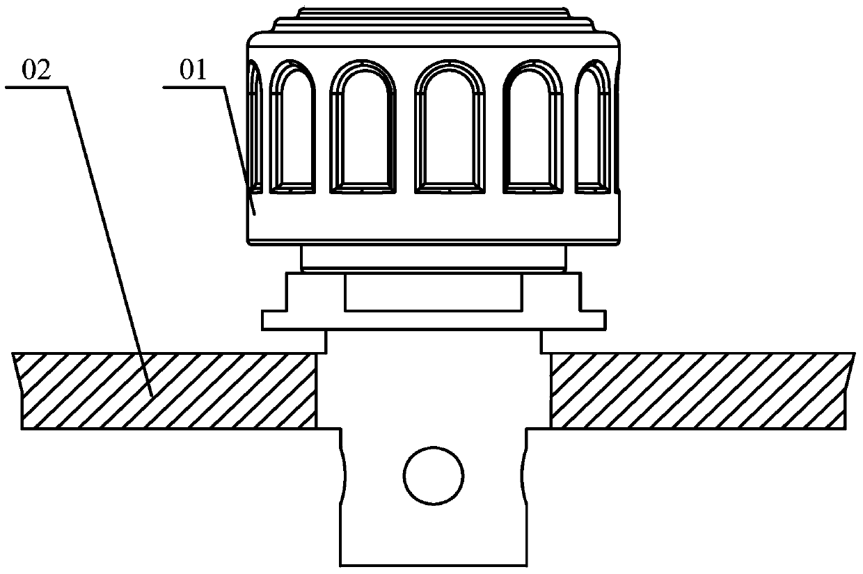
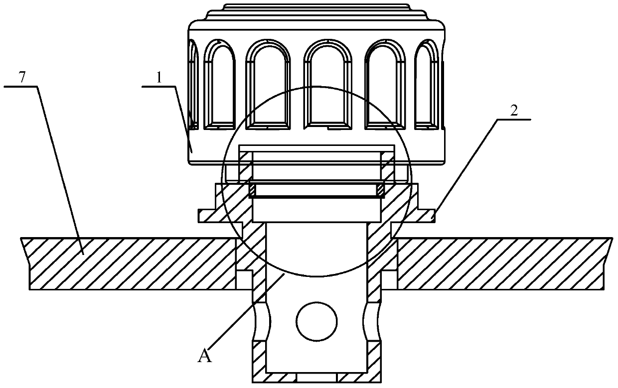
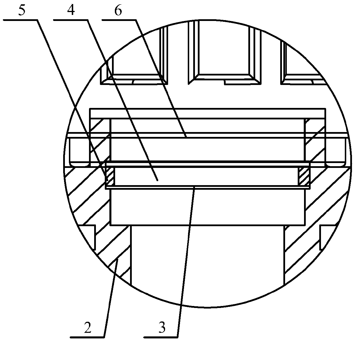
[0027] Please refer to Figure 2 to Figure 4 , in a specific embodiment, the vent cap provided by the present invention includes a vent cap body 1, a filter element 4, and a connector 2, and the vent cap body 1 is provided with a first vent hole connecting the internal cavity of the device with the outside atmosphere, connecting Part 2 is provided with a second vent hole, the second vent hole is a stepped hole, the two ends of the second vent hole are respectively connected with the first vent hole and ...


PUM


Abstract

The invention discloses a ventilation cap. The ventilation cap comprises a ventilation cap body, filter elements and a connecting part. The ventilation cap body is provided with a first vent hole which communicates an inner cavity of a device with the outside atmosphere. The connecting part is provided with a second vent hole which is a stepped hole. The two ends of the second vent hole are communicated with the first vent hole and the inner cavity of the device respectively. The two ends of the connecting part are used for being connected with the ventilation cap body and the device in a sealed mode respectively. The stepped hole is gradually tapered from top to bottom. The filter elements are mounted at the step of the stepped hole. Accordingly, according to the ventilation cap provided by the present invention, by arranging the connecting part provided with the filter elements, liquid in the device is effectively prevented from overflowing through the ventilation cap; thus, the oil leakproof performance of the ventilation cap is improved. The invention further discloses a speed reducer comprising the ventilation cap.

Description

technical field [0001] The invention relates to the technical field of ventilation devices, in particular to a ventilation cap. The present invention also relates to a speed reducer comprising the above-mentioned breather cap. Background technique [0002] In devices such as reducers and transmitters, the temperature of the internal components of the box rises during operation, causing the air in the box to expand and the air pressure in the box to rise. For example, a reducer is a device that matches the speed and transmits torque between the prime mover and the working machine or the actuator. During the working process, when the reducer is running for a long time, the temperature in the box will rise, resulting in deceleration. The gas inside the machine expands. In order to avoid excessive pressure inside the reducer box and damage the internal components of the reducer, it is usually necessary to install a vent cap on the reducer to release the gas in the reducer and ...

Claims


Application Information

Patent Timeline
Patent Type & Authority Patents(China)
IPC IPC(8): F16H57/027
Inventor 胡炜
Owner WORLD TRANSMISSION TECH TIANJIN SHARE LTD
Why Eureka
Try Eureka