
Method and device used for controlling internal temperature of refrigeration equipment

A technology for refrigeration equipment and internal temperature, applied in household refrigeration equipment, lighting and heating equipment, applications, etc., can solve problems such as reducing the service life of temperature adjustment units, manual adjustment by users of mechanical refrigerators, affecting the work of power grid equipment, etc., to avoid Service life, avoid too long or too short boot time, reduce the effect of impact

Inactive Publication Date: 2016-04-13
SUZHOU ELE MFG
View PDF3 Cites 0 Cited by
  • Summary
  • Abstract
  • Description
  • Claims
  • Application Information

AI Technical Summary

Problems solved by technology

[0003] This traditional mechanical refrigerator control mode has the following disadvantages: First, the thermostat gear of the mechanical refrigerator needs to be manually adjusted by the user.
Due to the error of the magnetic sensitive switch, it cannot be precisely controlled, and there is still a risk of poor refrigeration in winter and a very large power consumption in summer
[0004] In addition, in traditional refrigeration equipment, when the temperature regulation units such as compressors and low-temperature compensation heating wires start or stop at the non-zero crossing point of the alternating voltage, it will have an impact on the power grid and affect the work of other equipment in the power grid. At the same time, it will also reduce the service life of the thermostat itself

Method used


Image

  • Method and device used for controlling internal temperature of refrigeration equipment
  • Method and device used for controlling internal temperature of refrigeration equipment
  • Method and device used for controlling internal temperature of refrigeration equipment

Examples


Embodiment Construction

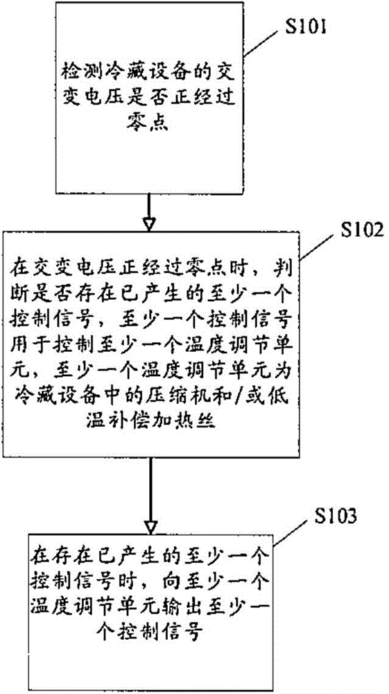
[0021] figure 1 A flow chart of a method for controlling the internal temperature of a refrigeration device according to an embodiment of the present invention is shown.

[0022] As shown in the figure, in step S101 it is detected whether the alternating voltage of the refrigeration equipment is passing through zero. For example, it can directly detect the voltage between the live wire and the neutral wire or detect the voltage between the live wire and the neutral wire that has been stepped down by a transformer.

[0023] In step S102, when the alternating voltage is passing through the zero point, it is judged whether there is at least one control signal that has been generated, the at least one control signal is used to control at least one temperature adjustment unit, and the at least one temperature adjustment unit is the refrigeration equipment compressor and / or low temperature compensating heating wires in the

[0024] In step 103, when there is at least one generated...


PUM


Abstract

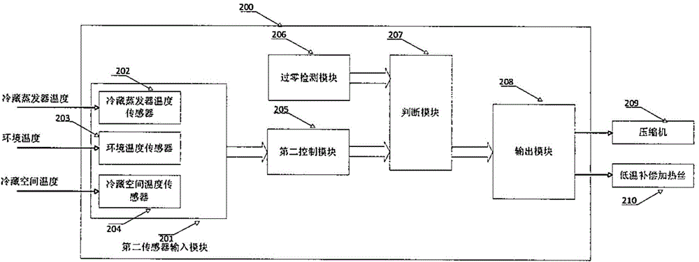
The invention relates to a method and device used for controlling internal temperature of refrigeration equipment. The method comprises following steps of: c) detecting whether alternating voltage of the refrigeration equipment exceeds zero; d), judging whether at least one generated control signal is present when alternating voltage exceeds zero; and e) outputting at least one control signal to at least one temperature regulation unit when at least one generated control signal is present. In the step d), at least one control signal is used for controlling at least one temperature regulation unit and the at least one temperature regulation unit is a compressor of the refrigeration equipment and / low-temperature compensation heating wires. Based on the technical scheme, the method and device used for controlling internal temperature of the refrigeration equipment have following beneficial effects: impact of temperature regulation units of the refrigeration equipment to a power grid is recued; temperature regulation units can be rapidly controlled; and overly long or short boot time caused by the low-temperature compensation heating wires is avoided because a user regulates shifts of a temperature controller.

Description

technical field [0001] The present invention relates to the field of refrigeration equipment control, in particular, the present invention relates to a method and device for controlling the internal temperature of a refrigeration equipment and a refrigeration equipment having the device or applying the method. Background technique [0002] In the traditional control mode of refrigerating equipment, for example, in a mechanical refrigerator, the start and stop of the compressor of the refrigerator depends on the switch of the thermostat. A temperature-sensing head is arranged on the thermostat, and a switch of the thermostat can be turned on or off according to the temperature of the temperature-sensing head, thereby controlling the compressor of the refrigerator. When the season changes, the user needs to manually adjust the gear position of the thermostat so that the control mode is adapted to different ambient temperatures. In addition, the low temperature compensation he...

Claims


Application Information

Patent Timeline
IPC IPC(8): F25D29/00
Inventor 田春波湛江
Owner SUZHOU ELE MFG
Learn More