
Wall switch function member

A technology of wall switches and functional parts, which is applied to the parts of flip switches/rocker switches, etc., and can solve the problems of easy breakage of support blocks, damage of pointed heads, and difficulty in assembly.

Inactive Publication Date: 2016-04-13
浙江苍岳电器有限公司
View PDF6 Cites 0 Cited by
  • Summary
  • Abstract
  • Description
  • Claims
  • Application Information

AI Technical Summary

Problems solved by technology

To solve the disadvantages in the prior art that the functional parts of the wall switch are not easy to assemble, the support blocks at both ends of the rocker toggle block are easy to break, and the pointed head at the lower end of the movable terminal is easily damaged by the impact of the copper rocker during assembly, etc.

Method used


Image

  • Wall switch function member
  • Wall switch function member
  • Wall switch function member

Examples


Embodiment 1

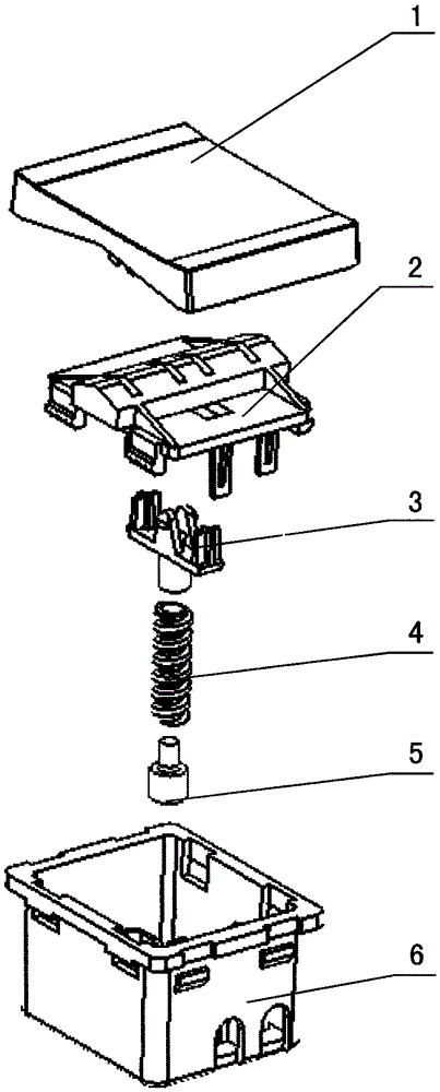
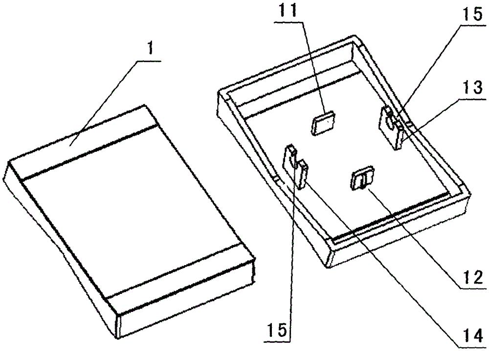
[0018] Example as image 3 and Image 6 As shown: there is no reinforcing rib 24 for clamping the switch button 1 on the housing cover plate 2, so the switch button 1 of embodiment 1 is clamped on the reinforcing rib on the mounting hole on the panel decoration frame, and The wall switch functional part is buckled on the frame, and the panel decorative frame is also buckled on the frame to realize the linkage between the up and down pressing columns (11, 12) of the switch button 1 and the upper and lower support blocks (31, 32) on the wall switch functional part ;

Embodiment 2

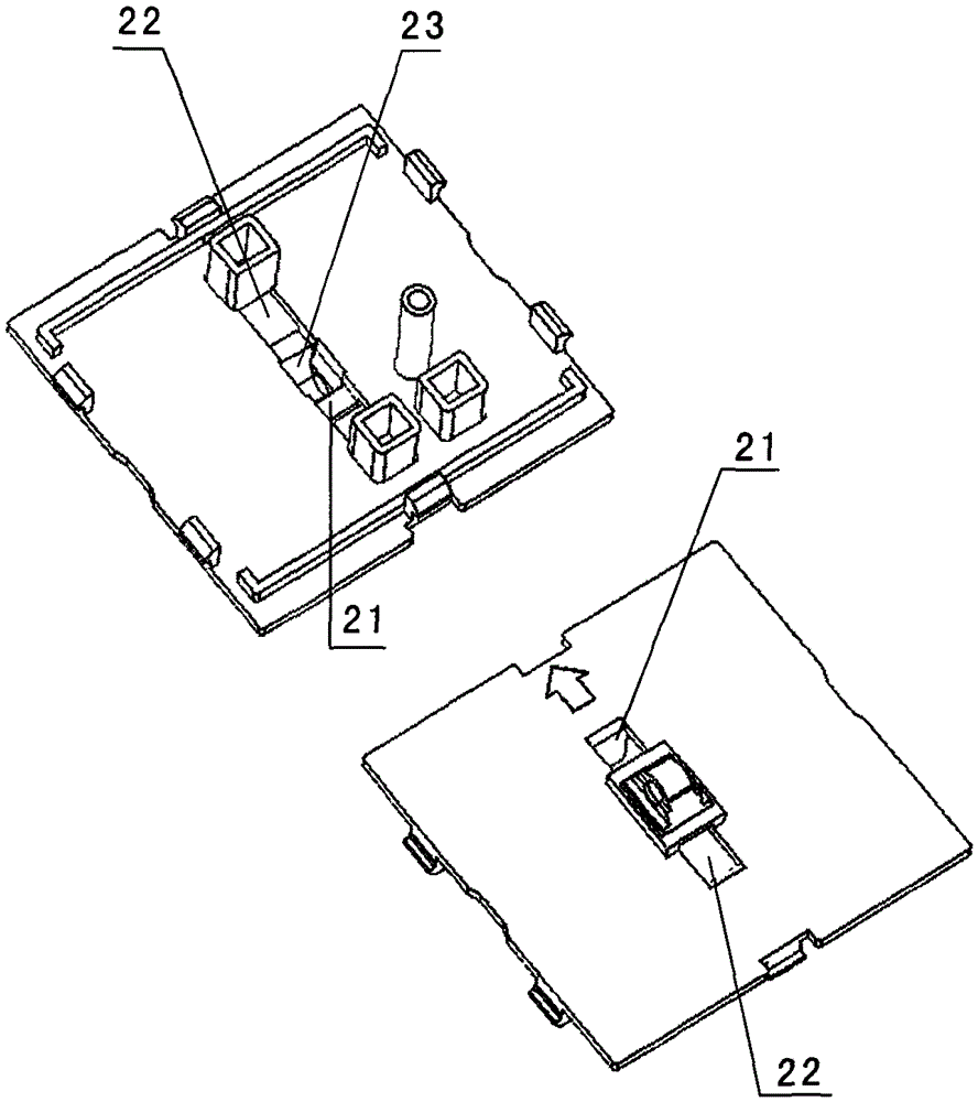
[0019] Example two such as Figure 4 and Figure 7 As shown: a wall switch functional part, which is characterized in that: a reinforcing rib 24 for clamping the switch button 1 is also provided on the front of the housing cover plate 2, and the reinforcing rib 24 is arranged in the through hole of the upper support block 21 and the through hole 22 of the lower support block, and at the left and right ends of the reinforcing rib 24, there is a left clamping groove 25 and a right clamping groove 25 for inserting the left and right clamping pins (13, 14) on the back of the switch button 1. Clamp groove 26, in the left clamp groove 25 and the right clamp groove 26 of reinforcing rib 24, a column 27 for clamping the left and right clamp feet (13, 14) of the switch button 1 is arranged, correspondingly An opening circular groove 15 matched with a cylinder 27 is provided on the left and right clamping feet (13, 14) of the switch button. The wall switch functional part of this embo...


PUM


Abstract

A wall switch function member mainly comprises a housing (6), a housing cover plate (2), a rocker dial block (3), a spring (4), a movable terminal (5), and a terminal, a rocker plate and a rocker plate support that are disposed in the housing. The wall switch function member is characterized in that the rocker dial block (3) is installed on and buckled to the housing cover plate (2) from bottom to top through a dial rotary column (33) to dial a clamping groove (23) of the rotary column. The beneficial effects are as follows: (1), the wall switch function member effectively solves the problems of a conventional wall switch function member that the tip of the lower end of a movable terminal of a rocker dial block is liable to be impacted and damaged by a copper rocker plate to cause inaccurate supporting points of the rocker plate, deflection during swing, unsmooth swing of a switch, shortened service life and other disadvantages; (2) the wall switch function member effectively solves the problems of the conventional wall switch function member that supporting blocks on the two ends of the rocker dial block are muck likely to fracture because of being pressed and swung by pressing columns on a switch button for a long period of time; and (3) the wall switch function member has a more ingenious structure, is more reasonable and convenient to install and assemble, is improved in strength and prolonged in service life, etc.

Description

technical field [0001] The invention belongs to a wall switch, in particular to a wall switch functional part on the wall switch. Background technique [0002] The wall switch refers to the electrical switch installed on the wall, which is used to connect and disconnect the circuit and control the switch of the lighting lamp. The movable terminal of the seesaw toggle block moves the seesaw to drive the seesaw in the wall switch function part to swing to realize the connection or disconnection between each terminal, thereby controlling the connection or disconnection of the circuit. Components such as terminal posts, seesaws, and seesaw brackets of the switch function are all set in a housing, and the housing and the cover of the housing are connected together by buckles. The seesaw in the traditional wall switch function The pulling block is usually installed above the front of the housing cover, that is, the rocker pulling block is usually installed from top to bottom from...

Claims


Application Information

Patent Timeline
IPC IPC(8): H01H23/16H01H23/04
CPCH01H23/04H01H23/16
Inventor 许通
Owner 浙江苍岳电器有限公司
Learn More