
Slag cooling device, slag cooling system and slag discharging method

A slag cooling device and slag cooling technology, which are applied in gasification process, lighting and heating equipment, petroleum industry, etc., can solve the problems of unreasonable slag cooling structure design, unsmooth slag discharge, and poor slag discharge stability.

Pending Publication Date: 2022-02-08
INST OF ENGINEERING THERMOPHYSICS - CHINESE ACAD OF SCI
View PDF0 Cites 0 Cited by
  • Summary
  • Abstract
  • Description
  • Claims
  • Application Information

AI Technical Summary

Problems solved by technology

[0003] At present, in the slag cooling system of the fluidized bed gasifier, due to the unreasonable design of the cooling slag structure, the slag discharge is not smooth, and the slag discharge is prone to bias flow and other technical problems such as poor slag discharge stability

Method used


Image

  • Slag cooling device, slag cooling system and slag discharging method
  • Slag cooling device, slag cooling system and slag discharging method
  • Slag cooling device, slag cooling system and slag discharging method

Examples


Embodiment Construction

[0059] In order to make the purpose, technical solutions and advantages of the present disclosure clearer, the present disclosure will be further described in detail below in conjunction with specific embodiments and with reference to the accompanying drawings.

[0060] Hereinafter, embodiments of the present disclosure will be described with reference to the drawings. It should be understood, however, that these descriptions are exemplary only, and are not intended to limit the scope of the present disclosure. In the following detailed description, for purposes of explanation, numerous specific details are set forth in order to provide a thorough understanding of the embodiments of the present disclosure. It may be evident, however, that one or more embodiments may be practiced without these specific details. Also, in the following description, descriptions of well-known structures and techniques are omitted to avoid unnecessarily obscuring the concepts of the present disclo...


PUM


Abstract

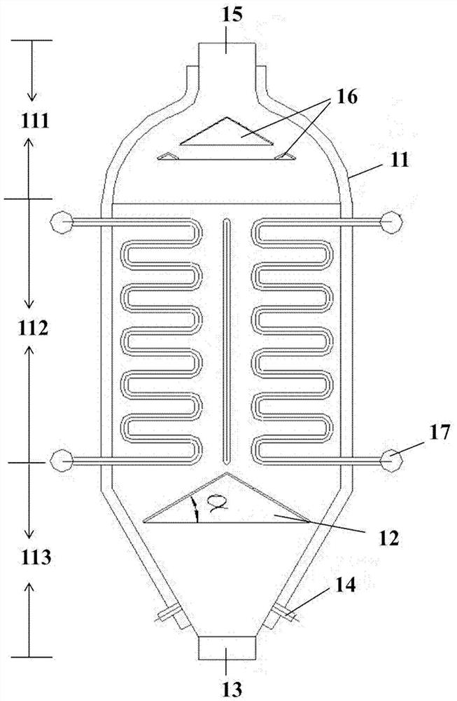
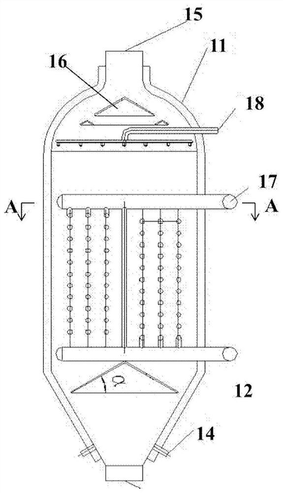
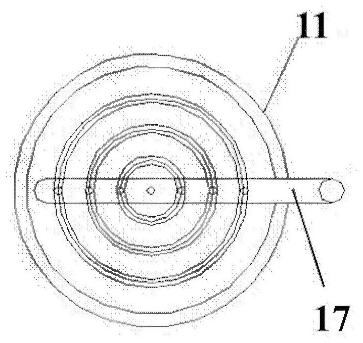
The invention provides a slag cooling device, a slag cooling system and a slag discharging method. On one hand, the slag cooling device comprises a shell of which the inner space is divided into a feeding area, a cooling area and a discharging area from top to bottom; a heat exchange unit which is arranged in the cooling area and is used for cooling slag from the feeding area; and a lower distributing device which is arranged in the discharging area and used for controlling the slag from the cooling area to be uniformly distributed and scattered to the discharging area and simultaneously bearing the gravity of the slag in the feeding area and the cooling area so as to prevent the slag from compacting a slag flow regulating valve to cause the failure of the slag flow regulating valve.

Description

technical field [0001] The present disclosure relates to the technical field of hydrocarbon fuel energy chemical industry, and in particular, the present disclosure relates to a slag cooling device, a slag cooling system and a slag discharging method. Background technique [0002] Coal gasification is one of the core technologies for clean and efficient utilization of coal, and it is the basis for the development of coal chemical process industries such as coal-based chemicals, coal-based clean fuels, industrial gas and polygeneration systems. The fluidized bed gasifier uses 0-10mm pulverized coal as the raw material, the gasification agent and the pulverized coal undergo gasification reaction in a fluidized form, and solid slag is discharged. The fluidized bed gasifier has the advantages of strong adaptability to coal types, no tar in the gas, and high gasification intensity. [0003] At present, in the slag cooling system of the fluidized bed gasifier, due to the unreason...

Claims


Application Information

Patent Timeline
Patent Type & Authority Applications(China)
IPC IPC(8): C10J3/72C10J3/56F28D21/00
CPCC10J3/72C10J3/56F28D21/00C10J2300/093F28D2021/0056
Inventor 董鹏飞湛月平朱治平王东宇柴祯张海霞
Owner INST OF ENGINEERING THERMOPHYSICS - CHINESE ACAD OF SCI
Learn More