Electronic device and composite antenna thereof

A technology of electronic devices and composite antennas, which is applied to antennas, antenna components, antenna supports/installation devices, etc., can solve problems such as high quality, increased cost, and difficult maintenance of antennas, and achieve the effect of ensuring communication quality

Active Publication Date: 2016-04-13
CHANGSHU HONGBO COMM TECH CO LTD
View PDF6 Cites 16 Cited by
  • Summary
  • Abstract
  • Description
  • Claims
  • Application Information

AI Technical Summary

Problems solved by technology

However, such a design of a traditional notebook computer requires extra space for both the frame and the headroom, which not only runs counter to the development trend of lightness, thinness, refinement, and compactness, but also inevitably increases excess costs in production.
In addition, since the frame and the headroom are located within the range that users can easily touch, they are easily interfered by the human body (that is, interference) during use, making it difficult for the antenna to maintain a high quality when transmitting and receiving radio. After the display body and the system body are relatively folded, it will cover the installation position of the antenna, so the radiation efficiency of the antenna will be significantly reduced due to the impact
It can be seen from this that, in view of the fact that the prior art has not yet reached the level of perfection that people expect for the design of the antenna relative to the electronic device, it is necessary to improve it. The technical solution to be introduced below is produced under this background

Method used


Image

  • Electronic device and composite antenna thereof
  • Electronic device and composite antenna thereof
  • Electronic device and composite antenna thereof

Examples


Embodiment Construction

[0027] In order to make the examiners of the patent office, especially the public, have a further understanding and understanding of the characteristics and the achieved effects of the present invention, the detailed description of the accompanying drawings is as follows:

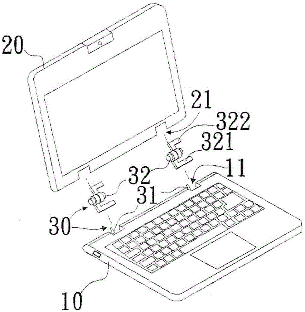
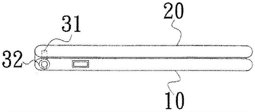
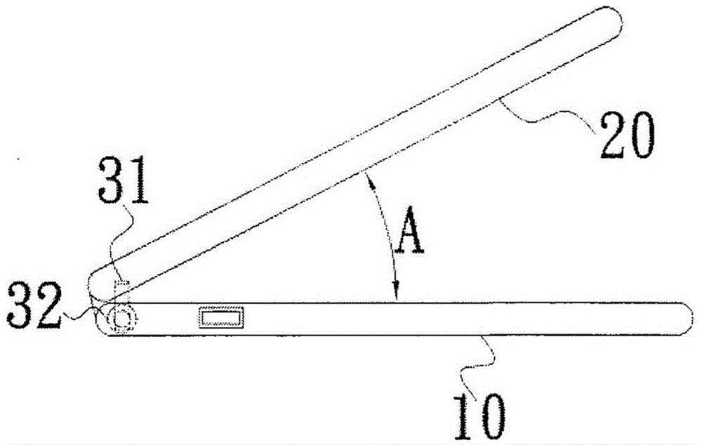
[0028] See figure 1 , which is a three-dimensional exploded view of an embodiment of the present invention, as shown in the figure, an electronic device of an embodiment of the present invention is a notebook computer, but the technology of the present invention can also be applied to other devices with rotating shafts Electronic devices, so the present invention is not only applicable to notebook computers. The notebook computer includes a system main body 10, a display main body 20 and two compound antennas 30, wherein the system main body 10 is the keyboard, computing circuit, memory and touch panel... etc. parts included in the notebook computer, and the display main body 20 is the screen part of the n...


PUM


Abstract

An electronic device and a composite antenna thereof belong to the technical field of an electronic product. The electronic device comprises a system main body, a display main body and the composite antenna, wherein the system main body is provided with a first groove and a ground surface, a radio-frequency signal ground end is arranged on the ground surface, the display main body is provided with a second groove, the composite antenna is provided with a first metal radiation body and a second radiation body, the first metal radiation body is arranged in the first groove and provided with a radio-frequency signal feed end, the radio-frequency signal feed end is arranged on a microwave substrate and near to the system main body, and the second metal radiation body is pivoted in a groove cavity jointly formed by the first groove and the second groove in a matching way and is taken as a rotation shaft of the display main body which is expanded, folded or turns over relative to the system main body. In the electronic device, a frame and a clearance zone are unnecessarily arranged to accommodate an antenna, and extra cost increase can be avoided; the composite antenna is accommodated in the grooves of the electronic device, the composite antenna can be prevented from interference of a human body when the electronic device is used, and ideal communication quality of the composite antenna during wireless radio wave transceiving can be guaranteed.

Description

technical field [0001] The invention belongs to the technical field of electronic products, specifically relates to an electronic device, and also relates to a compound antenna of the electronic device. Background technique [0002] With the rapid development of science and technology, various electronic products have been continuously introduced in recent years. Typical electronic devices such as notebook computers (used to be called "notebook computers", the same below), tablet computers, smart phones, personal digital assistants, etc. In addition to the continuous evolution in the world, the appearance is also developing towards the trend of lightness, thinness, refinement and ingenuity. Therefore, how to reduce the installation cost of related components with the electronic device as the carrier under the premise of taking into account the balance between the function and appearance of the electronic device has become the primary technical issue for the current research ...

Claims


Application Information

Patent Timeline
Patent Type & Authority Applications(China)
IPC IPC(8): H01Q1/22G06F1/16
CPCG06F1/1698H01Q1/22H01Q1/2258
Inventor 颜红方邱宗文魏嘉贤李荣耀
Owner CHANGSHU HONGBO COMM TECH CO LTD
Why Eureka
Try Eureka