Uplink synchronization method, device and system

A technology for synchronization devices and communication nodes, which is applied in the direction of synchronization devices, transmission systems, radio transmission systems, etc., and can solve the problems that the first communication node and the second communication node cannot communicate normally.

Active Publication Date: 2016-04-13
ZTE CORP
View PDF7 Cites 48 Cited by
  • Summary
  • Abstract
  • Description
  • Claims
  • Application Information

AI Technical Summary

Problems solved by technology

[0013] The present invention provides an uplink synchronization method, device and system, which solves the problem that the first communication node and the second communication node cannot communicate normally

Method used


Image

  • Uplink synchronization method, device and system
  • Uplink synchronization method, device and system
  • Uplink synchronization method, device and system

Examples


Embodiment 1

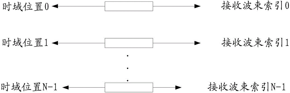
[0142] Assume that the base station uses N uplink receiving beams to receive uplink access signals, and the receiving beams can cover the area required by the base station.

[0143] The base station and the terminal predefine N time-domain resource sets corresponding to N uplink receive beam indexes respectively.

[0144] Alternatively, the base station notifies the corresponding relationship between the N time-domain resource sets and the N uplink receiving beam groups respectively through broadcasting and / or high-layer signaling. The base station notifies the terminal through broadcasting, or another base station under the same coverage that has established a connection with the terminal notifies the terminal through high-level signaling.

[0145] If the terminal obtains the corresponding relationship between N time-domain resource sets and N uplink receiving beam groups respectively through broadcast and or high-level signaling, then the terminal needs to first receive the ...

Embodiment 1

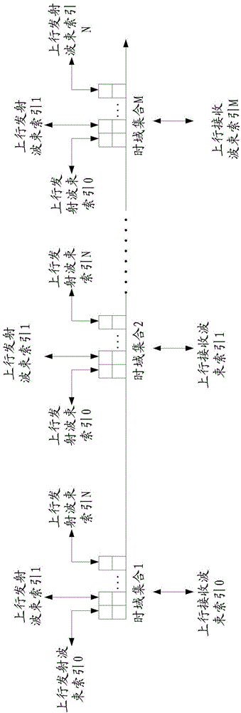
[0150] It is assumed that the base station uses 8 uplink receiving beam groups to basically cover the uplink receiving area that the base station needs to cover. The base station and the terminal pre-define 8 resource sets corresponding to the 8 uplink receiving beam groups, or the base station notifies the terminal of the corresponding relationship between the 8 time domain resource sets and the 8 uplink receiving beam groups through broadcasting and / or high-level signaling. As shown in Table 1. The time domain resource set may include an occupied time unit index and / or duration. The duration can be represented by the number of time units included. The duration may also be the time domain repetition times of the uplink access signal.

[0151] Table 1

[0152] Uplink receiving beam group index

Time-domain resource set for sending uplink access signals

0

Time Domain Resource Set 0

1

Time Domain Resource Set 1

7

Tim...

Embodiment 2

[0163] It is assumed that the base station uses 16 uplink receiving beam groups to basically cover the uplink receiving area that the base station needs to cover. The base station and the terminal pre-define 16 time-domain resource sets corresponding to the 16 uplink receiving beam groups, or the base station notifies the terminal of the correspondence between the 16 time-domain resource sets and the 16 uplink receiving beam groups through broadcast and / or high-level signaling relationship, as shown in Table 3.

[0164] The base station can notify the terminal through the broadcast and / or high-level signaling carrier of the base station, or another base station under the same coverage that has established a connection with the terminal can notify the terminal through high-level signaling.

[0165] The time domain resource set may include an occupied time unit index and / or duration. The duration can be represented by the number of time units included. The duration may also be...


PUM


Abstract

The invention provides an uplink synchronization method, device and system, relates to an LTE-Advanced system, and solves the problem that a first communication node and a second communication node cannot normally communicate. The method includes that: the first communication node configures resource set information corresponding to N uplink receiving wave beam groups, wherein the N is greater than 0, and each uplink receiving wave beam group includes at least one uplink receiving wave beam; the first communication node detects and receives an uplink access signal on resource sets corresponding to one or a plurality of receiving wave beams according to the resource set information; and after the first communication node detects the uplink access signal, the first communication node sends uplink access response information to the uplink access signal which meets an uplink access condition. The technical scheme is suitable for the LTE-Advanced system, configuration confirmation of both communication parts on the uplink access wave beams can be achieved.

Description

technical field [0001] The present invention relates to a long term evolution advanced system (Longtermevolution advanced system, LTE-Advanced) in the communication field, and in particular to an uplink synchronization method, device and system for realizing uplink receive beam index processing. Background technique [0002] In the millimeter wave communication system, due to the use of high carrier frequency for data transmission, the average path loss will be larger than that of the LTE system. For example, the carrier frequency of 28GHz is used for transmission, using the formula: [0003] L f = ( 4 πR λ ) 2 [0004] Wherein, R is the radius covered by the cell, and λ is the wavelength of the corresponding carrier. [0005] The calculated average ratio information of...

Claims


Application Information

Patent Timeline
Patent Type & Authority Applications(China)
IPC IPC(8): H04B7/06H04B7/08
CPCH04B7/04H04W56/0005H04W56/001H04W72/21H04B7/0617H04B7/0623H04L5/0053H04W16/28H04W72/0446H04W72/0453H04W72/046H04W72/0466
Inventor 刘文豪郭森宝毕峰郁光辉鲁照华
Owner ZTE CORP
Why Eureka
Try Eureka