Multi-stage perforating pressurizing device

A pressurization device and perforation technology, which is applied in the field of TCP tubing transmission perforation in oil and gas wells, can solve the problems of poor reliability, safety, multiple interlayer guns, and high operating intensity, so as to maintain the movement schedule, avoid mutual interference, and achieve high Effects of Precision Cut

Active Publication Date: 2011-04-20
CHINA PETROLEUM LOGGING CO LTD +1
View PDF9 Cites 18 Cited by
  • Summary
  • Abstract
  • Description
  • Claims
  • Application Information

AI Technical Summary

Problems solved by technology

[0004] The main problems in the perforating process with interlayer guns are: for perforating with large intervals and multi-layer sections, there are many interlayer guns, the workload is large, the operation intensity is high, the cost is high, and there are many explosion transmission links and low reliability.
The main problems in the staged perforation process with multiple pressure ignition heads are: the casing needs to be pressurized for perforation, and when re-perforating an old well that has been perforated, the formation communicates with the casing, and it is impossible to pressurize for negative pressure perforation. And the well killing fluid enters the formation during pressurization, which may contaminate the formation
The mai

Method used


Image

  • Multi-stage perforating pressurizing device
  • Multi-stage perforating pressurizing device
  • Multi-stage perforating pressurizing device

Examples


Embodiment Construction

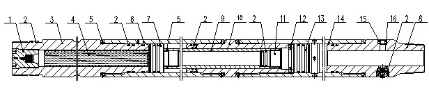
[0034] A multi-stage perforation pressurization device, including a diaphragm igniter and pressurized propellant, and also includes a power casing and a pressurization casing located at the lower part of the power casing, a power chamber is arranged in the power casing, and a There is a pressurized chamber, and the power chamber communicates with the pressurized chamber. The partition igniter and the pressurized powder mechanism located at the lower part of the partition igniter are arranged in the power chamber, and the power generated by the power chamber is provided in the pressurized chamber. The booster piston is driven, the booster piston is connected to the piston through the push rod, and the piston is fixed on the intermediate joint through the shear pin.

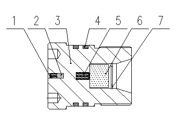
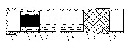
[0035] The clapboard igniter includes a cap, a clapboard body, an O-ring and a collar, and the clapboard body is provided with a donor-end charge hole and an acceptor-end charge hole filled with gunpowder. The igni...


PUM


Abstract

The invention discloses a multi-stage perforating pressurizing device. The device comprises a power shell and a pressurizing shell positioned on the lower part of the power shell, wherein a power cavity is formed in the power shell; a pressurizing cavity is formed in the pressurizing shell; the power cavity is communicated with the pressurizing cavity; a diaphragm igniter and a pressurizing gunpowder mechanism positioned on the lower part of the diaphragm igniter are arranged in the power cavity; a pressurizing piston driven by power generated by the power cavity is arranged in the pressurizing cavity and is connected with a piston through a push rod; and the piston is fixed on an intermediate joint through a shear pin. The stability and controllability of pressure generated by the combustion of gunpowder in the pressurizing cavity can be ensured; the pressure is applied to the pressurizing piston, so that the pressurizing piston moves stably; pressure increment is generated in an interlayer oil pipe, so that a next stage pressure initiation device and a next stage perforating gun are reliably detonated; and the multi-stage perforating pressurizing device is used for the pressure multi-stage perforating process, is suitable for various well conditions, and particularly can meet the requirements of a high-inclination well and a horizontal well on multi-section, large-distance and negative pressure perforating.

Description

technical field [0001] The invention relates to the field of oil and gas well TCP tubing transmission perforation, in particular to a multi-stage perforation booster device. Background technique [0002] In the petroleum industry, oil well perforation operation is an important process, which is to lower the perforating gun into the target layer in the well, use the detonating device to detonate, and after detonation, the shaped charge will penetrate the perforating gun, casing and cement layer. The exit channel connects the stratum with the oil well, so that the formation oil and gas can flow into the oil well smoothly. [0003] Multi-stage perforation technology refers to the perforation technology that penetrates multiple oil and gas layers at one time in the case of the next pipe string, which can reduce the number of perforations and save operating time and cost. The conventional multi-stage perforation operation methods are the perforation process with interlayer gun, ...

Claims


Application Information

Patent Timeline
IPC IPC(8): E21B43/119E21B43/1185
Inventor 曹宇欣唐其林吴泽林徐锐项宏君李雅萍
Owner CHINA PETROLEUM LOGGING CO LTD
Why Eureka
Try Eureka