Bus communication receiver decoding circuit

A decoding circuit and bus communication technology, applied in the field of bus communication and bus communication receiving end decoding circuit, can solve the problems of slow charging and discharging speed, fast charging and discharging speed, increased cost, etc., to achieve stable voltage, good charging and discharging current, good charging and discharging control effect

Active Publication Date: 2018-11-27
CRM ICBG (WUXI) CO LTD
View PDF6 Cites 0 Cited by
  • Summary
  • Abstract
  • Description
  • Claims
  • Application Information

AI Technical Summary

Problems solved by technology

[0005] 1. Since the level of the comparison threshold has nothing to do with the bus voltage, the interference on the bus cannot be responded with the comparison threshold at the same time. As a result, when the master sends instructions through the bus, the slave receives the wrong instruction because it uses the absolute comparison threshold.
[0006] 2. Because it is a networked circuit, it is restricted by the different lengths of the actual space bus. In the communication mode, it is necessary to set different parameters for the slaves at different positions so that they can uniformly receive the instructions sent by the master, increasing the cost, time
[0009] Although the structure of the receiving circuit can maintain the voltage of VCAP through the capacitor, due to the existence of R3, the charge of C1 will be discharged through R3. The size of R3 is very restricted. If R3 is too large, the charging and discharging speed is too slow, which will cause the voltage rise of C1 to be too high. Slow, R3 is too small, the charging and discharging speed is too fast, causing the voltage of C1 to drop too fast

Method used


Image

  • Bus communication receiver decoding circuit
  • Bus communication receiver decoding circuit
  • Bus communication receiver decoding circuit

Examples


Embodiment Construction

[0033] In order to describe the technical content of the present invention more clearly, further description will be given below in conjunction with specific embodiments.

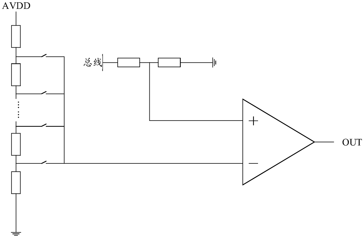
[0034] The present invention adopts the method of relative percentage comparison, which eliminates the differences caused by the different lengths of the connecting wires between the slaves closest to and farthest from the master, and also makes each slave use the same setting value to avoid different different slaves use different settings.

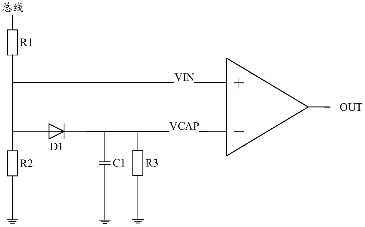
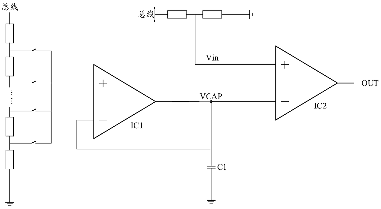
[0035] The bus communication receiver decoding circuit of the present invention includes: a first bus voltage divider module, which is used to input the divided voltage generated after the bus voltage is stepped down to the positive input terminal of the first comparator; a threshold voltage generation module , used to generate a threshold voltage according to the bus voltage, and the threshold voltage is input to the inverting input terminal of the first comparator; ...


PUM


Abstract

The present invention relates to a bus communication receiving end decoding circuit. The bus communication receiving end decoding circuit comprises: a first bus voltage division module configured to input voltage division voltage generated after the bus voltage reduces the voltage into the positive input end of a first comparator; a threshold-voltage generation module configured to generate a threshold voltage according to the bus voltage, and inputting the threshold voltage to the reverse input end of the first comparator; the first comparator configured to allow a host to be standby or emit an instruction according to the size of the threshold voltage and the size of the voltage division voltage. Through adoption of the structure, the bus communication receiving end decoding circuit is able to eliminate the difference caused by different lengths of connection lines of slave computers being nearest to the host and being farthest to the host, and allow each slave computer to employ the same set values, so that the problem is solved that different slave computers use different set values.

Description

technical field [0001] The present invention relates to the technical field of communication, in particular to bus communication, in particular to a decoding circuit for a receiving end of bus communication. Background technique [0002] When a common networked circuit communicates with the host, it generally adopts an absolute voltage comparison method to accept the instructions sent by the host, divide the bus level and reduce it to an acceptable range for the circuit, and then compare the bus with an absolute voltage value. The sent level signal judges the command sent by the bus by comparing the results. The existing mode does not take into account the impact of the loss of the connecting line on the bus when the connecting line between the master and the slave is too long. [0003] see figure 1 As shown, the voltage division of AVDD generates an absolute level that has nothing to do with the bus voltage, as the comparison threshold, compared with the voltage division l...

Claims


Application Information

Patent Timeline
Patent Type & Authority Patents(China)
IPC IPC(8): H04L12/40
CPCH04L12/40H04L12/40006
Inventor 王磊张天舜曾洁琼邱旻韡周宇捷张钧吴君磊
Owner CRM ICBG (WUXI) CO LTD
Why Eureka
Try Eureka