
Slide rail locking mechanism

A locking mechanism and slide rail technology, applied in furniture parts, household utensils, drawers, etc., can solve the problems of reducing the service life of electromagnets and wasting energy, and achieve the effects of increasing stability, saving energy, and improving service life

Active Publication Date: 2016-04-20
雅固拉国际精密工业(苏州)有限公司
View PDF5 Cites 3 Cited by
  • Summary
  • Abstract
  • Description
  • Claims
  • Application Information

AI Technical Summary

Problems solved by technology

In the prior art, the locking is achieved through the conduction of the electromagnet and the adsorption of the deadbolt, which requires continuous conduction of the electromagnet to achieve locking, which will reduce the service life of the electromagnet and waste energy

Method used


Image

  • Slide rail locking mechanism
  • Slide rail locking mechanism
  • Slide rail locking mechanism

Examples


Embodiment Construction

[0033] The present invention will be described in detail below with reference to the accompanying drawings and in combination with embodiments.

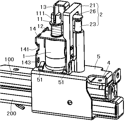
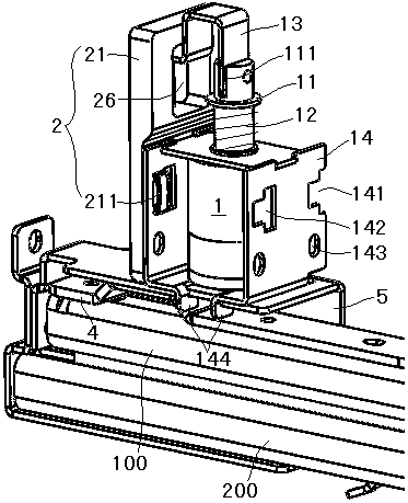
[0034] refer to figure 1 As shown, a sliding rail locking mechanism includes an electromagnet 1 arranged on one side of the inner rail 100, and the electromagnet 1 includes an iron core 11 and a first spring 12 connected to the iron core 11. The iron core 11 A pressing piece 13 is connected to the top, and the other end of the pressing piece 13 is arranged above the push self-locking mechanism 2 with intermittent locking function. Lock groove 41 is arranged. The inner rail 100 is connected with a lock slot frame 4 protruding from one side of the inner rail 100 , and the lock slot frame 4 is provided with the lock slot 41 . Pressing the intermittent locking function of the self-locking mechanism 2 enables the electromagnet 1 to be turned on once to realize locking, and to be turned on again to realize unlocking, which reduces the fr...


PUM


Abstract

The invention discloses a slide rail locking mechanism. The slide rail locking mechanism comprises an electromagnet arranged on one side of an inner rail, wherein the electromagnet comprises an iron core and a first spring connected onto the iron core; a press piece is connected onto the iron core, and the other end of the press piece is arranged above a press self-locking mechanism with an intermittent locking function; a bolt is arranged below the press self-locking mechanism; a lock groove is formed in the inner rail. By means of the intermittent locking function of the press self-locking mechanism, locking can be realized through one-time conduction of the electromagnet, unblocking can be realized through next conduction, the use frequency of the electromagnet is reduced, so that the service life of the slide rail locking mechanism is prolonged, and energy can be saved.

Description

technical field [0001] The invention relates to a sliding rail locking mechanism. Background technique [0002] The sliding rail locking mechanism is used to lock the sliding rail to prevent it from being pulled out. In the prior art, the electromagnet conducts and absorbs the dead bolt to realize locking, and the electromagnet needs to be continuously conducted to realize locking, which will reduce the service life of the electromagnet and waste energy. Contents of the invention [0003] The purpose of the present invention is to overcome the above problems in the prior art, and provide a slide rail locking mechanism, which can be locked by powering on once, and unlocked by powering on again, so as to prolong the service life of the electromagnet and save energy. [0004] In order to achieve the above-mentioned technical purpose and achieve the above-mentioned technical effect, the present invention is realized through the following technical solutions: [0005] A slidi...

Claims


Application Information

Patent Timeline
IPC IPC(8): A47B88/00A47B88/16
CPCA47B88/00
Inventor 王招娣毛春朱健华
Owner 雅固拉国际精密工业(苏州)有限公司
Learn More