
Engine start control apparatus

Inactive Publication Date: 2016-10-13
TOYOTA JIDOSHA KK
View PDF6 Cites 15 Cited by
  • Summary
  • Abstract
  • Description
  • Claims
  • Application Information

AI Technical Summary

Benefits of technology

The invention provides an engine start control apparatus that can enhance the durability of a starting device and reliably restart an engine. The apparatus predicts when the engine is about to restart and selects between three different start controls based on the predicted condition. The first control is for cranking the engine, the second control is for carrying out fuel injection and ignition, and the third control is for rotating the crankshaft with the aid of the external force from the driving wheel side. This reduces the driving current and the frequency of use of the starting device, improving its durability. Additionally, if the vehicle speed is high or the brakes are on, the apparatus selects the second path with the large resistance to further reduce the driving current and prevent unintended acceleration. Overall, this system improves the reliability of the starting device and reduces the frequency of use.

Problems solved by technology

However, Japanese Patent Application Publication No. 2010-23660 (JP 2010-23660 A) does not take a deterioration in the electric motor into account, and there is room for improvement.

Method used


Image

  • Engine start control apparatus
  • Engine start control apparatus
  • Engine start control apparatus

Examples


first embodiment

[0028]The engine start control apparatus according to the invention will be described with reference to FIGS. 1 to 4.

[0029]FIG. 4 is a general view showing a vehicle and the engine start control apparatus according to the first embodiment of the invention. A vehicle Ve as a subject of the first embodiment of the invention is equipped with an engine (ENG) 1 as a motive power source, an automatic transmission (T / M) 2, an output shaft 3, a differential 4, an axle 5, and driving wheels 6. The engine 1 is a well-known internal combustion engine such as a gasoline engine, a diesel engine or the like, and is configured as a direct injection type in which fuel is injected into cylinders. The automatic transmission 2 is a well-known transmission that can automatically change the speed ratio and that can be automatically set in a neutral state.

[0030]In the vehicle Ve, a crankshaft (not shown) of the engine 1 is connected to an input shaft 2a of the automatic transmission 2. Besides, a motive ...

second embodiment

[0064]FIG. 6 is a general view showing a vehicle and the engine start control apparatus according to the invention. The vehicle Ve is equipped with a clutch C between the engine 1 and the automatic transmission 2 in a motive power transmission path. The clutch C is a friction clutch having a pair of engagement elements that are selectively engaged or released. In the clutch C, one of the engagement elements (a frictional engagement element on an input side) is coupled to the crankshaft of the engine 1, and the other engagement element (a frictional engagement element on an output side) is coupled to the input shaft of the automatic transmission 2. In the vehicle Ve, the engine 1 is decoupled from a motive power transmission system by releasing the clutch C, so no torque can be transmitted between the engine 1 and the driving wheels 6. Besides, the engine 1 is connected to the motive power transmission system by engaging the clutch C, so torque can be transmitted between the engine 1...


PUM


Abstract

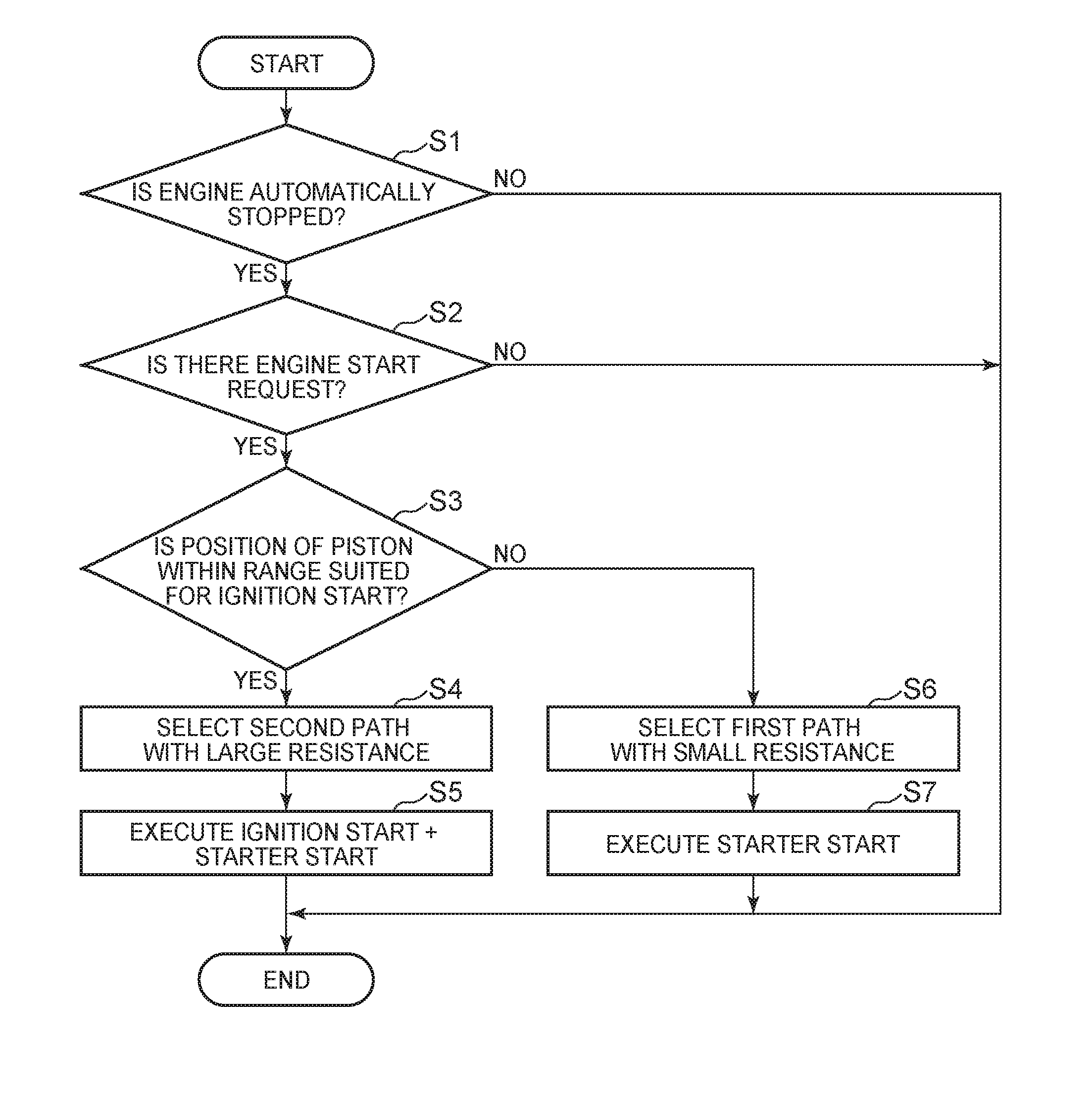
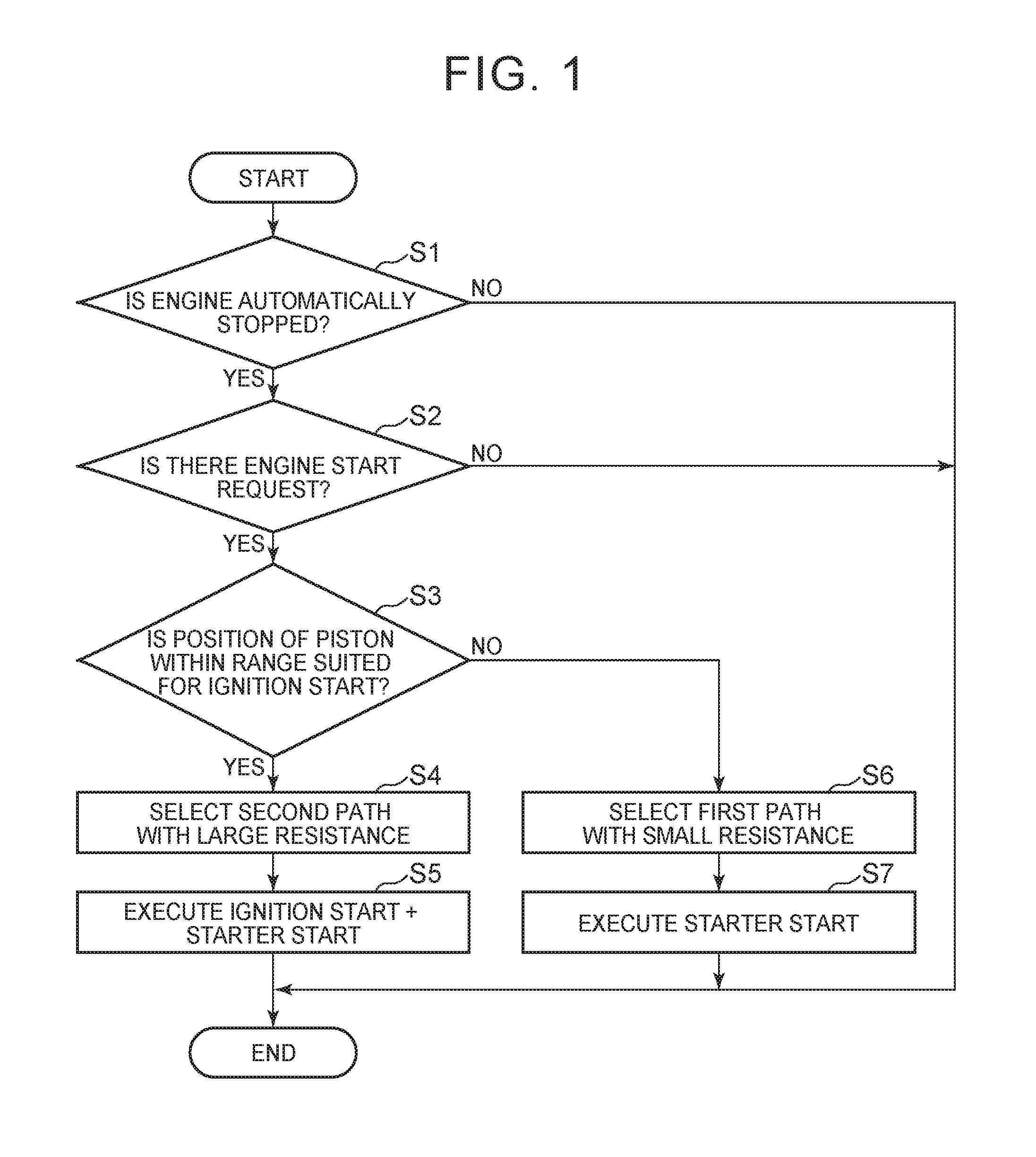
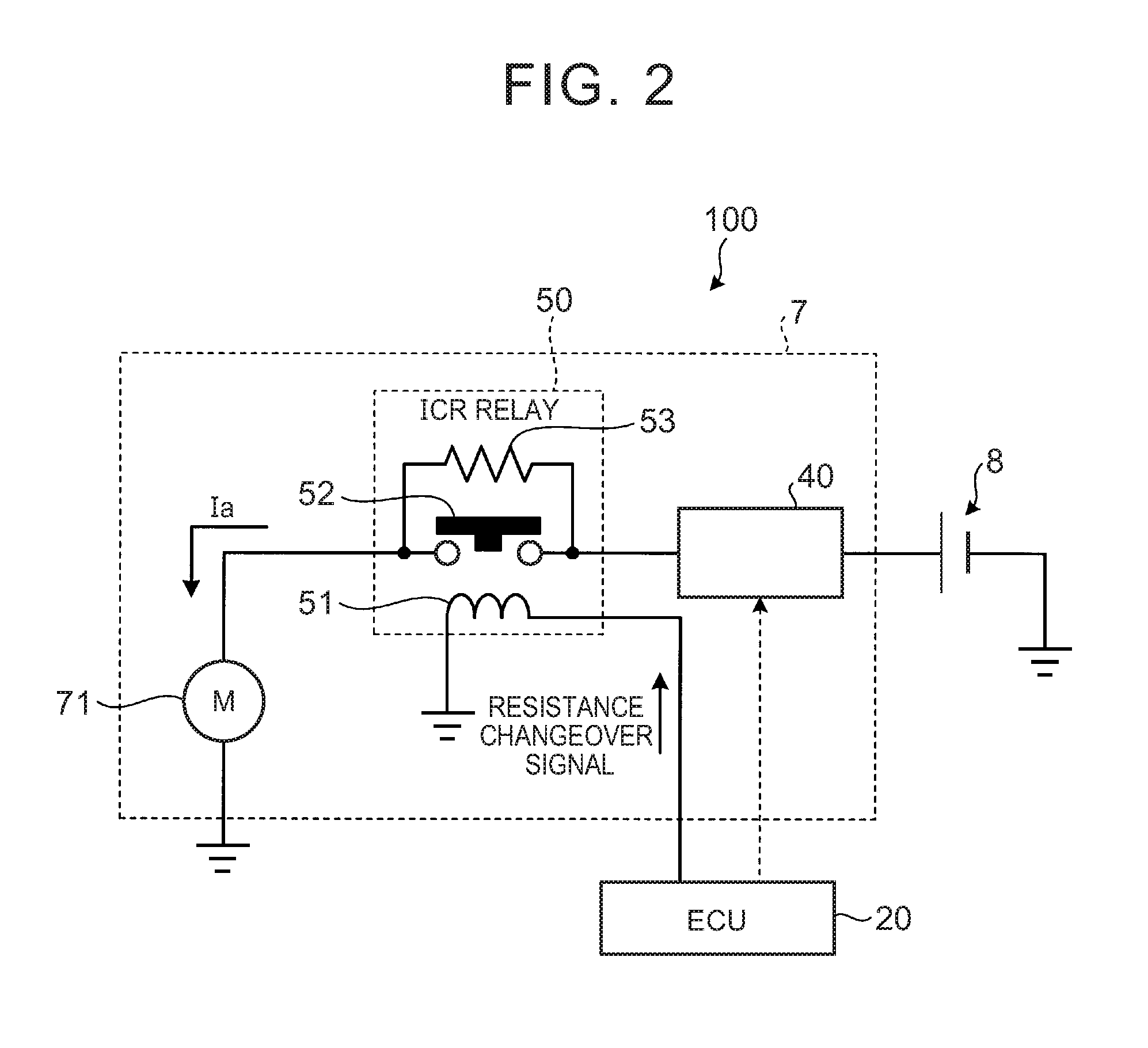
An engine start control apparatus for a vehicle in which an engine can be automatically stopped temporarily is characterized in that when the position of a piston is within a range that is likely to cause ignition during automatic stop of the engine (Yes in step S3), it is predicted that the electric power consumed in a starting device in restarting the engine is small, a second path with a large resistance is selected as an energization path from a battery to a starter motor (step S4), and starter start for cranking the engine by the starting device and ignition start based on fuel injection and ignition are executed (step S5) to restart the engine.

Description

INCORPORATION BY REFERENCE[0001]The disclosure of Japanese Patent Application No. 2015-080284 filed on Apr. 9, 2015 including the specification, drawings and abstract is incorporated herein by reference in its entirety.BACKGROUND OF THE INVENTION[0002]1. Field of the Invention[0003]The invention relates to an engine start control apparatus.[0004]2. Description of Related Art[0005]Conventionally, there is known a control apparatus that automatically stops an engine of a vehicle when a predetermined automatic stop condition is fulfilled.[0006]For example, it is described in Japanese Patent Application Publication No. 2010-23660 (JP 2010-23660 A) that an engine is restarted upon fulfillment of a predetermined restart condition through the cranking by an electric motor and the combustion of fuel when prompt restart is prepared during automatic stop of the engine, and only through the cranking by the electric motor when prompt restart is not prepared during automatic stop of the engine.[...

Claims


Application Information

Patent Timeline
IPC IPC(8): F02D41/06F02N11/08
CPCF02D41/065F02N11/0862F02N11/087F02D2200/503F02N2300/2002F02D29/02F02N11/00F02D2200/501F02D41/009F02N11/0803F02N11/0814F02N19/005F02N99/002F02N2200/021F02N2200/046F02N2200/0801F02N2200/102F02N2300/106Y02T10/40
Inventor MATSUSHITA, KOKI
Owner TOYOTA JIDOSHA KK
Learn More