Vibrating screen rubber spring installation structure and rubber spring replacement method
A technology of rubber spring and installation structure, which is applied to low internal friction springs, springs/shock absorbers, chemical instruments and methods, etc., can solve the problems that rubber springs cannot be stretched, noise, etc., and achieves quick and convenient disassembly and replacement. Noise, the effect of prolonging the service life
- Summary
- Abstract
- Description
- Claims
- Application Information
AI Technical Summary
Problems solved by technology
Method used
Image
Examples
Embodiment 1
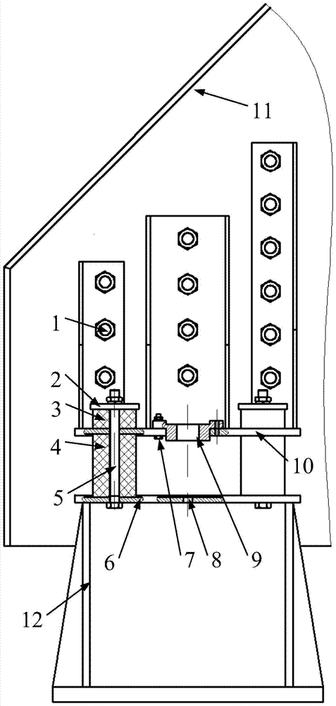
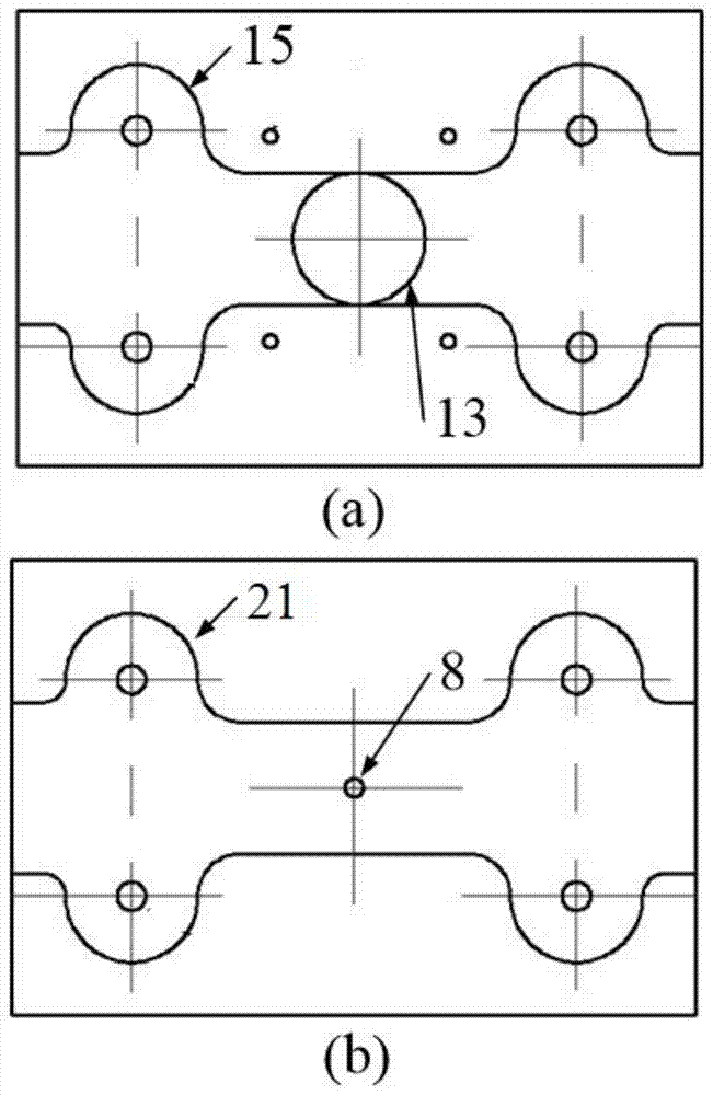
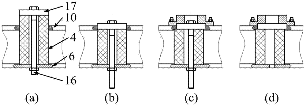
[0036] as attached figure 1 As shown, the rubber spring installation structure of the vibrating screen includes a screen box 11, an installation base 12, an upper support plate 10, a lower support plate 6, replacement accessories, and at least two sets of damping mechanisms; the upper support plate 10 is fixed on the screen box by bolts 1 11, the lower support plate 6 is fixed on the installation base 12; the upper support plate 10 and the lower support plate 6 are connected by a vibration damping mechanism, so that the screen box 11 can vibrate relative to the installation base 12; the vibration damping mechanism includes the first A high-strength bolt 5, a main rubber spring 4 pressed between the upper support plate 10 and the lower support plate 6, an auxiliary rubber spring 3 placed above the upper support plate 10, and a pressing plate 2 placed on the upper end of the auxiliary rubber spring 3, the first high The strength bolt 5 passes through the pressure plate 2, the au...
Embodiment 2
[0049] as attached Figure 4 As shown, the rubber spring installation structure of the vibrating screen includes a screen box 11, an installation base 12, an upper support plate 10, a lower support plate 6, replacement accessories, and at least two sets of damping mechanisms; the upper support plate 10 is fixed on the screen box by bolts 1 11, the lower support plate 6 is fixed on the installation base 12; the upper support plate 10 and the lower support plate 6 are connected by a vibration damping mechanism, so that the screen box 11 can vibrate relative to the installation base 12; the vibration damping mechanism includes the first A high-strength bolt 5, a main rubber spring 4 pressed between the upper support plate 10 and the lower support plate 6, an auxiliary rubber spring 3 placed above the upper support plate 10, and a pressing plate 2 placed on the upper end of the auxiliary rubber spring 3, the first high The strength bolt 5 passes through the pressure plate 2, auxil...
PUM
 Abstract
Description
Claims
Application Information
 - R&D
- Intellectual Property
- Life Sciences
- Materials
- Tech Scout
- Unparalleled Data Quality
- Higher Quality Content
- 60% Fewer Hallucinations
Browse by: Latest US Patents, China's latest patents, Technical Efficacy Thesaurus, Application Domain, Technology Topic, Popular Technical Reports.
© 2025 PatSnap. All rights reserved.Legal|Privacy policy|Modern Slavery Act Transparency Statement|Sitemap|About US| Contact US: help@patsnap.com


